4 i/oports/control panel connectors – SUPER MICRO Computer X6DHT-G User Manual
Page 27
Chapter 2: Installation
2-7
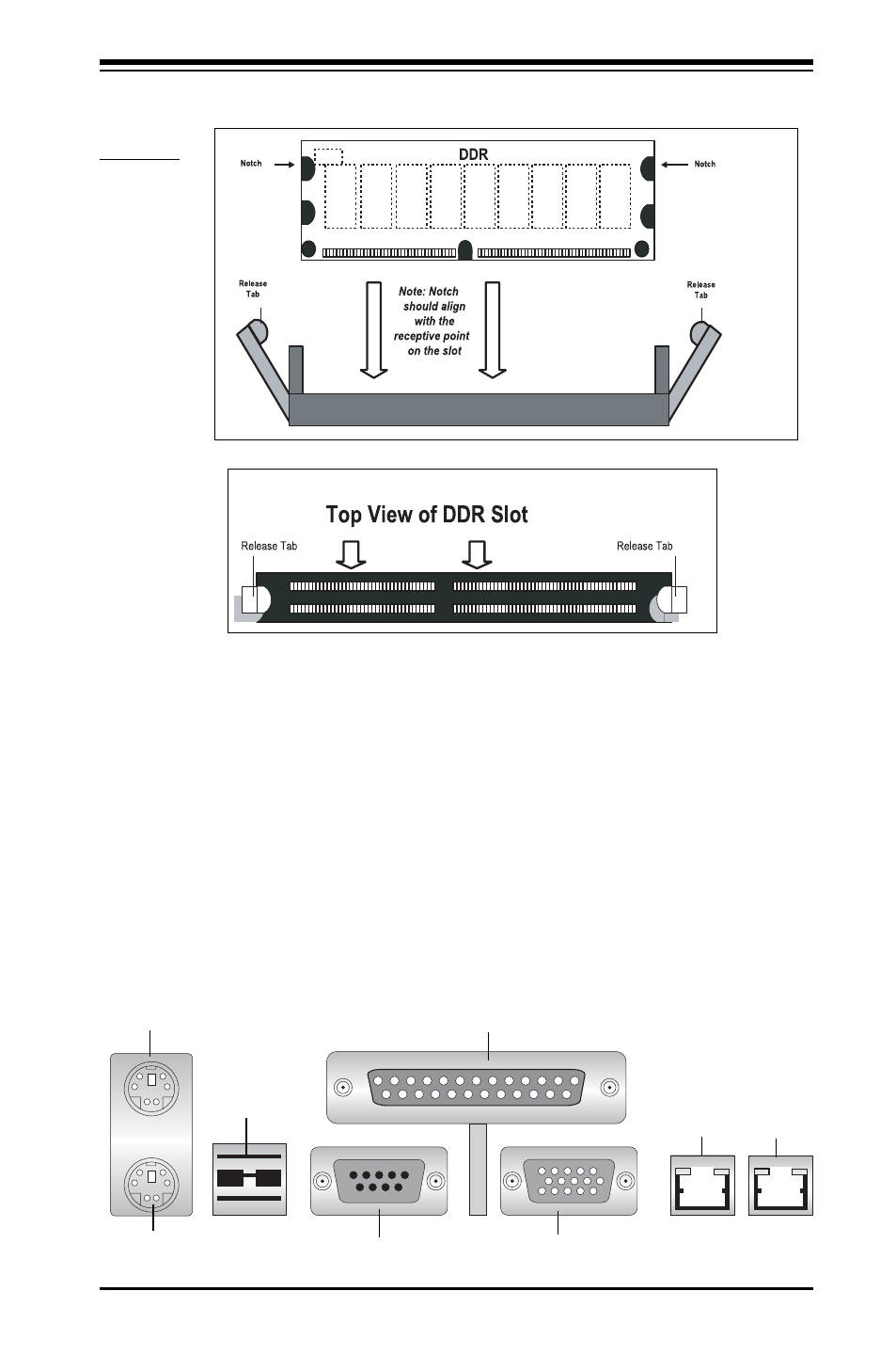
To Remove:
Use your thumbs to gently push near the edge of both ends
of the module. This should release it from the slot.
2-4
I/OPorts/Control Panel Connectors
The I/O ports are color coded in conformance with the PC 99 specification.
See Figure 2-3 below for the colors and locations of the various I/O ports.
Figure 2-3. I/O Port Locations and Definitions
Figure 2-2. Installing and Removing DIMMs
To Install: In-
s e r t m o d u l e
vertically and
p r e s s d o w n
until it snaps
i n t o p l a c e .
Pay attention
t o t h e a l i g n -
ment notch at
the bottom.
Mouse (Green)
Keyboard (Purple)
USB 0/1
COM1
Video
Parallel Port
LAN1
LAN2