Snapper Front Implement Lift Kit 1691195 User Manual
Page 2
10. See figure
the left and right tubes (5
6) to the front tubes (9, IO) using the tees
11. Underneath tractor, notice that the front half of
frame is connected to rear half of frame. Locate the
front capscrews that connect the frame halves.
Secure the front tubes and clips (13, figure 3) to
each
using the lockwashers and nuts
12, figure 3).
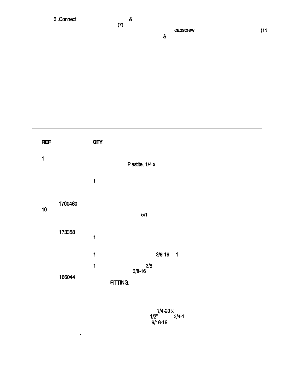
PART
NO.
NO.
2
3
4
5
6
7
6
9
11
12
13
14
15
16
17
16
19
20
21
22
23
24
* 26
26
27
26
29
171165
1960106
1675968
175731
1676401
1676400
1700033
1700125
1674734
1922007
1909509
1677267
1677105
1677104
166017
1921210
173360
1916965
1916950
1701406
1675769
1708166
927769
1679063
1921963
921409
1
1
1
1
1
2
2
1
1
2
2
2
2
1
2
2
1
1
1
2
1
2
1
1
1
DESCRIPTION
KNOB, Control Handle
SCREW,
1
CONTROL LEVER ASSY.
BUSHING
TUBE ASSY., Right
TUBE ASSY., Left
UNION, Tee, 37
CAP
TUBE ASSY., Front, Left
TUBE ASSY., Front, Right
NUT, Hex Jam,
6-I 4
LOCKWASHER, Int. Tooth
CLIP, Tube
BODY ASSY., Female
BRACKET, Quick Disconnect, L.H.
BRACKET, Quick Disconnect, R.H.
RING, Retaining
CAPSCREW, Hex Hd.,
x
PLUG, Plastic
LOCKWASHER,
NUT, Hex,
CLAMP, Hose
90 Swivel
FITTING, 90
VALVE ASSY., 2 Spool
RING, Retaining
LINK, Control
CAPSCREW, Hex Hd.,
2
FITTING, Hyd. Short
tube x
6 (For use with Early
Model Tractors wlth
Valve Port)
*Standard Seal Repair Kit Part No. 1679733
Form 1701802