Installation, New actuators, remove pre-load, Removing preload – Siemens ASC77.2U User Manual
Page 2: Preparing the actuator shaft adapter
Document No. 129-420
Installation Instructions
December 13, 2004
Installation
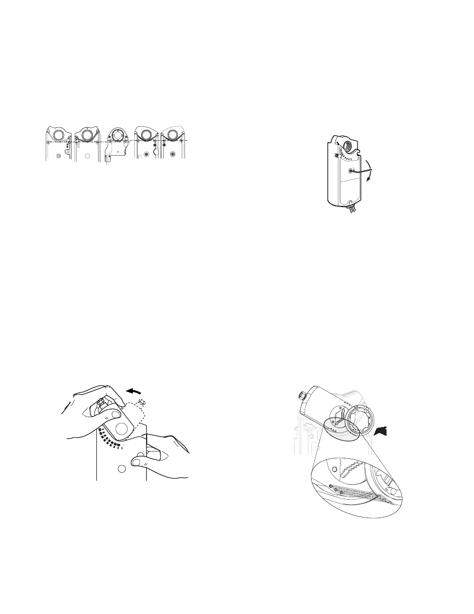
New Actuators, Remove Pre-load
GCA, GBB, GIB
GMA, GEB
EA1
179R1
Figure 3. Determine Actuator Model and Orientation.
NOTE: For in-service actuators, skip Removing Pre-
load. For new actuators, remove the factory-
installed 5° pre-load.
Removing Preload
Before the External Auxiliary Switch can be installed on
a new, out-of-the-box actuator, you must remove the
factory-installed preload.
New Non-Spring Return Actuators
1. Insert shaft adapter at position A (See Figure 4).
2. Press the manual override button and move the
shaft adapter counterclockwise until actuator
reaches the internal stop (actuator will not move
past this point).
3. Remove the shaft adapter and manually reinstall it
against the external end stop at position B (See
Figure 4).
4. Proceed with EAS installation.
90
90
EA1190R1
PUSH
Figure 4.
Insert Shaft Adapter at Position A.
New Spring Return Actuators
1. Without the shaft adapter installed, using the hex
wrench, wind the manual override one full
revolution and release the wrench (See Figure 5).
The actuator will return to the 0° position and the
preload is now removed.
EA1192R1
1-Turn
Manual
Override
Figure 5.
2. Manually install the shaft adapter against the
external stop on the left end of the actuator. (See
position B in Figure 4.)
Removing Factory Pre-load from New SR Actuator.
Preparing the Actuator Shaft Adapter
1. Remove the position indicator from an in-service
actuator.
2. Determine the appropriate position adapter ring
3. Align and snap the three open notches on the edge
of the EAS position adapter ring in place over the
three raised stubs on the actuator shaft adapter.
(See Figure 6).
B
EA1
177R1
NOTE:
GCA/GBB/GIB
models use the
larger ring.
GMA/GEB models
use smaller ring.
See Figure 1.
A
Figure 6. Attaching the EAS Position Adapter Ring.
Page 2 of 5
Siemens Building Technologies, Inc.