Johnson Controls SA PD 180 THRU 240 User Manual
Page 6
430645-YIM-D-0610
6
Johnson Controls Unitary Products
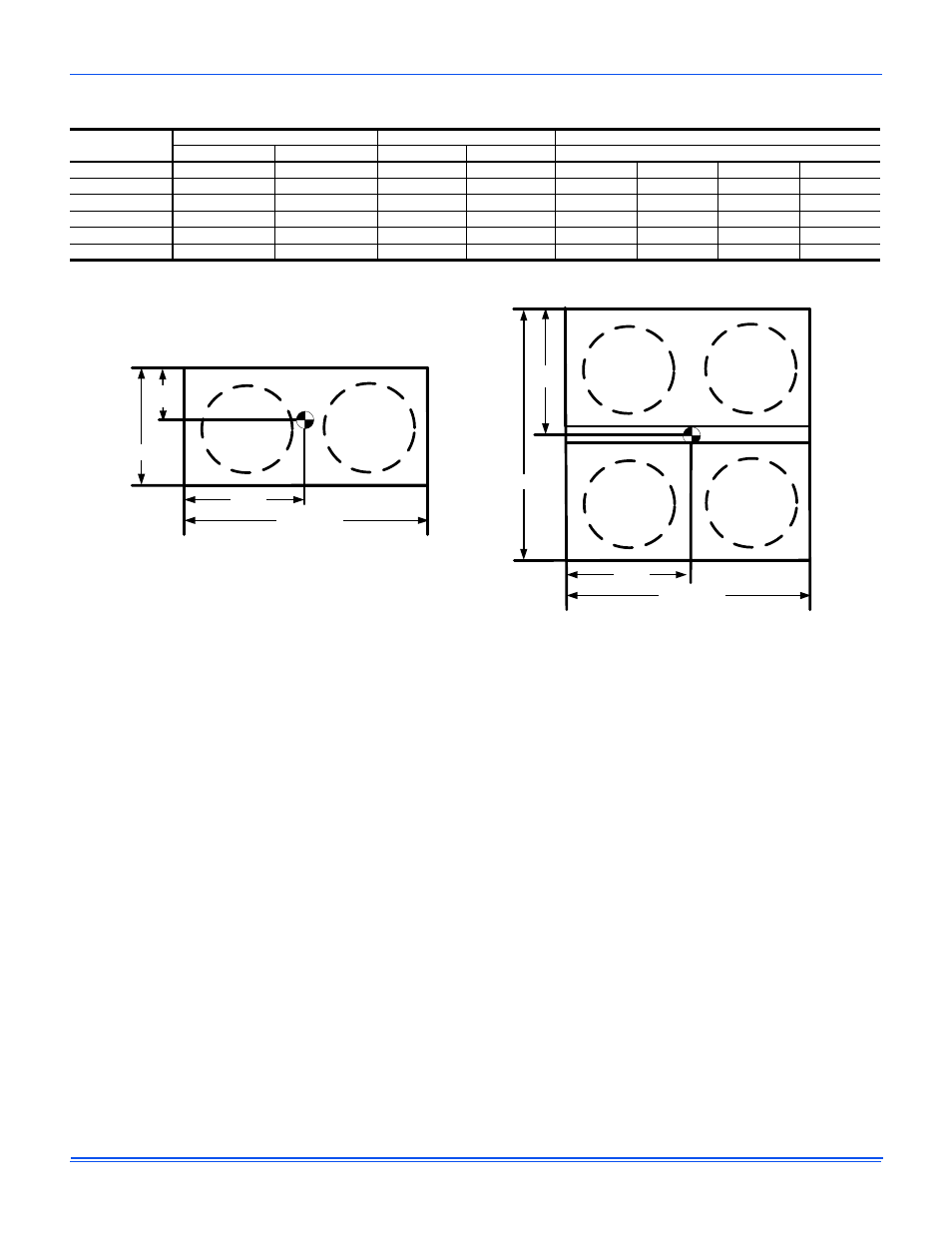
Figure 1: Corner Weights & Center Of Gravity
NOTE: Front of unit is considered the side having the control
box.
Concrete piers can also support ground level units. These piers
should (1) extend below the frost line, (2) be located under each
of the section's four corners, and (3) be sized to carry the load
of the corner it supports.
On either rooftop or ground level installations, rubber padding
can be applied under the unit to lessen any transmission of
vibration.
Holes are provided in the base rails for bolting the unit to its
foundation.
For ground level installations, precautions should be taken to
protect the unit from tampering and unauthorized persons from
injury. Screws on access panels will prevent casual tampering.
Further safety precautions such as a fenced enclosure or
locking devices on the panels may be advisable. Check local
authorities for safety regulations.
Table 3:
Corner Weights & Center of Gravity
Model
Weight (lbs.)
Center of Gravity (in.)
4 Point Load Location (lbs.)
Shipping
Operating
X
Y
A
B
C
D
PC090
421
430
17.3
33
110
130
103
87
PC120
543
574
16.4
32.3
153
161
134
127
PC180
947
968
32.5
33
266
274
217
211
PD180
921
942
34
32.5
243
275
225
199
PC240
1116
1152
32.1
30.8
300
301
276
275
PD240
1090
1126
31.2
31.8
311
295
253
267
DIM X
DIM Y
LENGTH
WIDTH
C
A
B
D
CG
FRONT
RIGHT
REAR
LEFT
CG
DIM X
DIM Y
LENGTH
WIDTH
C
B
A
D
FRONT
REAR
LEFT
RIGHT
PC090, PC120
PC180, PD180,
PC240, PD240