2 ignitor – JVC 335 User Manual
Page 14
Model 335 Supplement
14
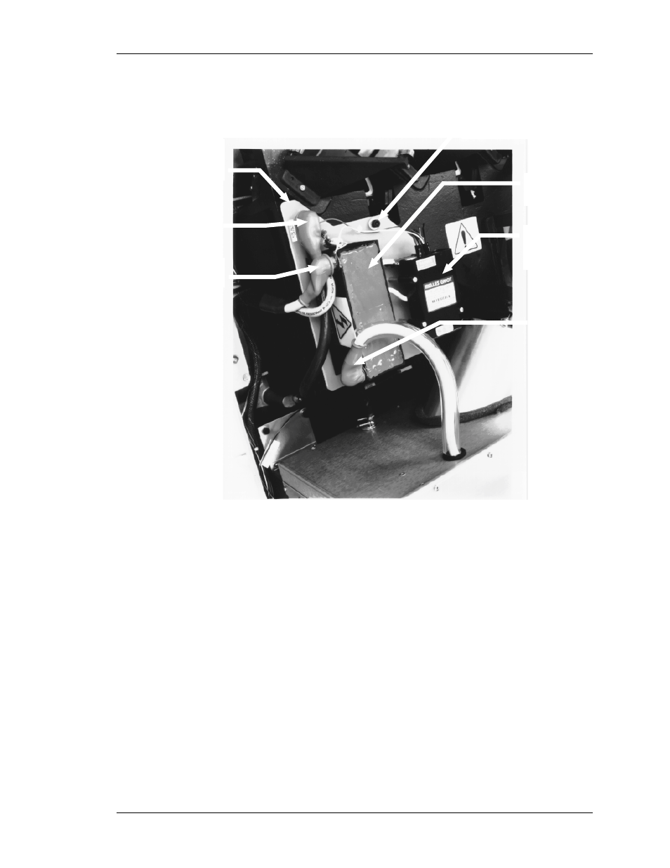
5.2 Ignitor
HIGH VOLTAGE
TRANSFORMER
LASER
POWER
SUPPLY
IGNITOR
MOUNTING
BOARD
POSITIVE
IN
POSITIVE
OUT
NEGATIVE
HEX SCREW
Figure 2. Ignitor Assembly.
The Ignitor Assembly consists of a Laser Power Supply, a High
Voltage Transformer and the associated wiring.
To remove the Ignitor Assembly:
1. Turn power off and unplug the projector.
2. Remove the front and rear covers.
3. Clearly label and remove the four (4) cables connected to the
Ignitor Assembly.
4. Remove the three (3) hex screws that attach the Ignitor
Mounting Board to the projector. NOTE: The larger washer
must be replaced to the hex screw at the left, front of the
Ignitor Mounting Board to allow space for the other component
that is connected there.
See also other documents in the category JVC Projectors:
- 1108TTH-AO-AO (120 pages)
- HD-Z70RX5 (34 pages)
- HD-P61R2U (96 pages)
- HD-65S998 (88 pages)
- DLA-G10U (15 pages)
- DLA-M5000SCU (68 pages)
- LCT2441-001B (162 pages)
- D-ILA DLA-RS40 (78 pages)
- LX-D1010 (4 pages)
- PC007182999-1 (185 pages)
- HD-70FH97 (96 pages)
- DLA-HX2U (62 pages)
- LCT2370-003A (64 pages)
- DLA-HD1 (55 pages)
- DLA-HD1 (108 pages)
- DLA-HD1 (2 pages)
- PC007182399-1 (62 pages)
- DLA-SH4K (48 pages)
- D-ILA DLA-HD350 (57 pages)
- HD-61G657 (88 pages)
- 370 SC (163 pages)
- I'Art Pro AV-56P786 (80 pages)
- 250 (190 pages)
- 1004KGI-II-IM (72 pages)
- LX-P1010ZU (79 pages)
- AV 56WP94 (88 pages)
- HD-55G456 (88 pages)
- HD-61FN97 (96 pages)
- I'Art 1004TNH-II-IM (72 pages)
- AV 48P777 (72 pages)
- CB100 (128 pages)
- HD-56FB97 (88 pages)
- AV 56WP74 (64 pages)
- BHL5006-S (4 pages)
- DLA-HD350 (58 pages)
- DLA-HD350 (173 pages)
- HD-61Z576 (80 pages)
- AV-56WP30 (68 pages)
- DLA-HX2E (62 pages)
- HD-ILA LCT2067-002A-A (96 pages)
- AVO48WP30 (68 pages)
- DLA-SX21U (58 pages)
- I'Art 1003-TN-II-IM (88 pages)
- AV-P960E (109 pages)