Rear view, Index – JVC DR-MH20SUJ User Manual
Page 13
Masterpage:Right+
EN
13
Filename [DR-MH30UJ_04Name.fm]
INDEX
Page 13
Monday, 12 July 2004 14:10
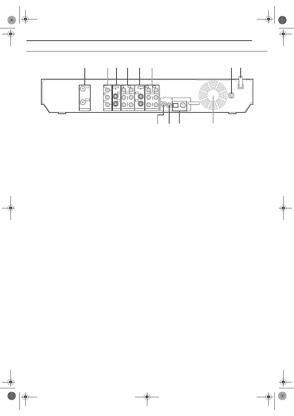
Rear View
A Antenna Connectors (ANTENNA IN/OUT)
B Component Video Output Connectors (COMPONENT
C S-video Output Connectors (S-VIDEO OUTPUT (L-1/
L-2))
D Video/Audio Output Connectors (VIDEO/AUDIO
OUTPUT (L-1/L-2))
E S-video Input Connectors (S-VIDEO INPUT (L-1/L-2))
F Video/Audio Input Connectors (VIDEO/AUDIO INPUT
G Region Number Label
H AC Power Cord
I Cable Box Control Connector (CABLE BOX)
J AV COMPU LINK Connector*
* Not function with this unit.
K Digital Audio Output Connectors
(DIGITAL OUT (OPTICAL/COAXIAL))
L Cooling Fan
● This prevents the temperature from rising inside the unit.
Do not remove it.
● Install the unit so as not to block the area around the fan.
● The cooling fan on the rear of the unit may be activated even if
the unit is turned off in the following cases;
— In the Automatic Satellite Program Recording standby mode
— when “AUTO CLOCK” is set to “ON” (
(Set “AUTO CLOCK” to “OFF” if you mind the noise of the fan.)
PCM STREAM
AV COMPU LINK
CABLE BOX
LEFT
AUDIO
RIGHT
LEFT
VIDEO
S-VIDEO
VIDEO
S-VIDEO
L-1
L-1
L-2
L-2
AUDIO
RIGHT
COMPONENT
COAXIAL
OPTICAL
IN
Y
P
B
P
R
OUT
DIGITAL OUT
ANTENNA
OUTPUT
INPUT
1
L-2
L-1
L-2
L-1
A
E F
C D
B
G H
J K
L
I
DR-MH30UJ_00.book Page 13 Monday, July 12, 2004 3:17 PM