Controls, indicators and connectors – JVC GVSP2 User Manual
Page 7
EN
5
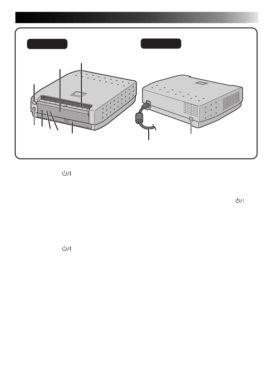
CONTROLS, INDICATORS AND CONNECTORS
1
STANDBY/ON
button
• Turns the printer on and off.
2
Ink Cassette Access Door
• Open this to load or unload the ink
cassette.
3
Paper outlet
• Prints are output from here.
4
PRINT DATA input connector
• Connect to the video camera's printer
output connector using the provided
printer cable.
5
STANDBY/ON
lamp
• Lights when the printer is turned on.
6
PRINT lamp
• Flashes when receiving image data.
Lights during printing.
7
ERROR lamp
• Indicates that an error has occurred in
the printer.
If this lamp lights or begins flashing,
check the message that is displayed on
the video camera.
8
Paper tray
• Insert papers here.
9
Power cable
• Plugs into household electrical outlet.
Always press the STANDBY/ON
button and turn off power before
unplugging the power plug from the
electrical outlet.
0
USB terminal
• Connects to the USB terminal on the PC
via a commercially available USB cable.
USB Interface Support
This printer supports USB (Universal
Serial Bus), the new standard serial
interface.
45 67
8
1
2
3
9
0
Rear View
Front View