JAI CV-M536 User Manual
Page 6
- 5 -
CV-M536/538/539
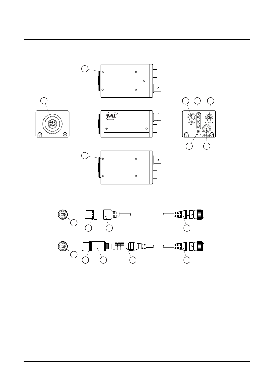
4. Locations and Functions
4-1. CCU
4-2. HEAD
a) CV-M536
b) CV-M538/539
1
12P connector
: To connect camera head with camera control unit
(For Camera Head)
2
Video output connector
: To output video VS1.0Vp-p
(BNC connector)
3
SW1 switch
: To set shutter speed and function modes
4
6-pin Multi connector
: Output WEN/EEN signal and input external trigger pulse, etc.
5
GAIN
: To adjust gain level
6
12P Multi connector
: Input DC+12V power and input/output of HD/VD signal, etc.
7
Screw holes for Tripod mount plate : To fix tripod mount plate (optional) on camera
8
CCD sensor
: 1/2" Hyper HAD Interline transfer CCD sensor
9
Focus adjustment ring
: To adjust lens focus
10 Camera head
11 Camera head connector
: To connect camera head with cable (Only for CV-M538/539)
12 12P connector
: To connect camera head with camera control unit
(For Camera Head)
&
'
%
%
!
"
#
$
&
'