Mode selector switch and cal function, Tandem operation: ggx master with ggx slaves – Johnson Controls M9220-GGX-3 User Manual
Page 9
M9220-GGx-3 Proportional Electric Spring Return Actuators Installation Instructions
9
Mode Selector Switch and CAL Function
The M9220-GGx-3 Proportional Electric Spring Return
Actuators are factory set at Direct Acting (DA), DC 0 to
10 V control input (Figure 13). To change to RA
operation, move the mode selection switch from DA to
RA. The DC input signal is selectable from
DC 0 to 10 V or from DC 2 to 10 V, which corresponds
to 0 to 90° rotation. If the rotation range is reduced, the
end-stop is reached with a reduced input signal. For
example, if a DC 0 to 10 V input signal is selected and
the rotation range is limited to 75°, the end-stop is
reached at DC 8.3 V. If an external 500 ohm resistor is
placed across the input (see Figure 10), the switch
positions then select between 0-20 mA or 4-20 mA.
The CAL function enables the actuator to redefine the
selected control input range proportionally across a
reduced rotation range. The actuator stores the
reduced rotation range in nonvolatile memory (retains
data when power is lost or removed).
To calibrate the control input range, proceed as follows:
1.
With power off, move the mode selection switch to
the CAL position (Figure 13). Then, energize the
actuator. The actuator automatically rotates until
the end-stops are found, and proportionally
reconfigures the control input range to the reduced
rotation range.
2.
Return the mode selection switch to the desired
selection (example: DA, 0 to 10 VDC control input).
Note: During normal operation, if the actuator
stroke increases due to seal or seat wear, the input
is redefined to the increased rotation range in
approximately 0.5° increments.
3.
If the actuator mounting position is changed or if
the linkage is adjusted, repeat Steps 1 and 2 to
reinitiate the CAL function.
Note: To repeat calibration with power applied, move
the mode selection switch out of the CAL position for at
least 2 seconds before returning it to the CAL position.
Auto calibration begins 5 seconds after you return it to
the CAL position.
Tandem Operation: GGx Master with
GGx Slaves
The tandem configuration (Figure 14 and Figure 16)
provides twice (with two actuators) or triple (with three
actuators) the running and spring return torque of a
single actuator, or 354 lb·in (40 N·m), 531 lb·in
(60 N·m). The actuators may be mounted in tandem
using the M9000-158 Tandem Mounting Kit. To mount
a third actuator, user-configured bracketing is required.
Follow these guidelines for tandem operation:
•
Two or three M9220-GGx-3 actuators may be
operated in tandem on the same shaft. If mounting
two actuators, see Figure 14; for three actuators,
see Figure 16.
•
Each actuator requires separate 24 volt power.
When two or more actuators connected in tandem
share a common power source, the total maximum
power draw is actually 1.5 times the normal
running current for each actuator.
(Total Power = Number of Actuators x Running
Power x 1.5).
•
Only one of the actuators can be configured as the
master. Set the selector switch to the master
position (Figure 15).
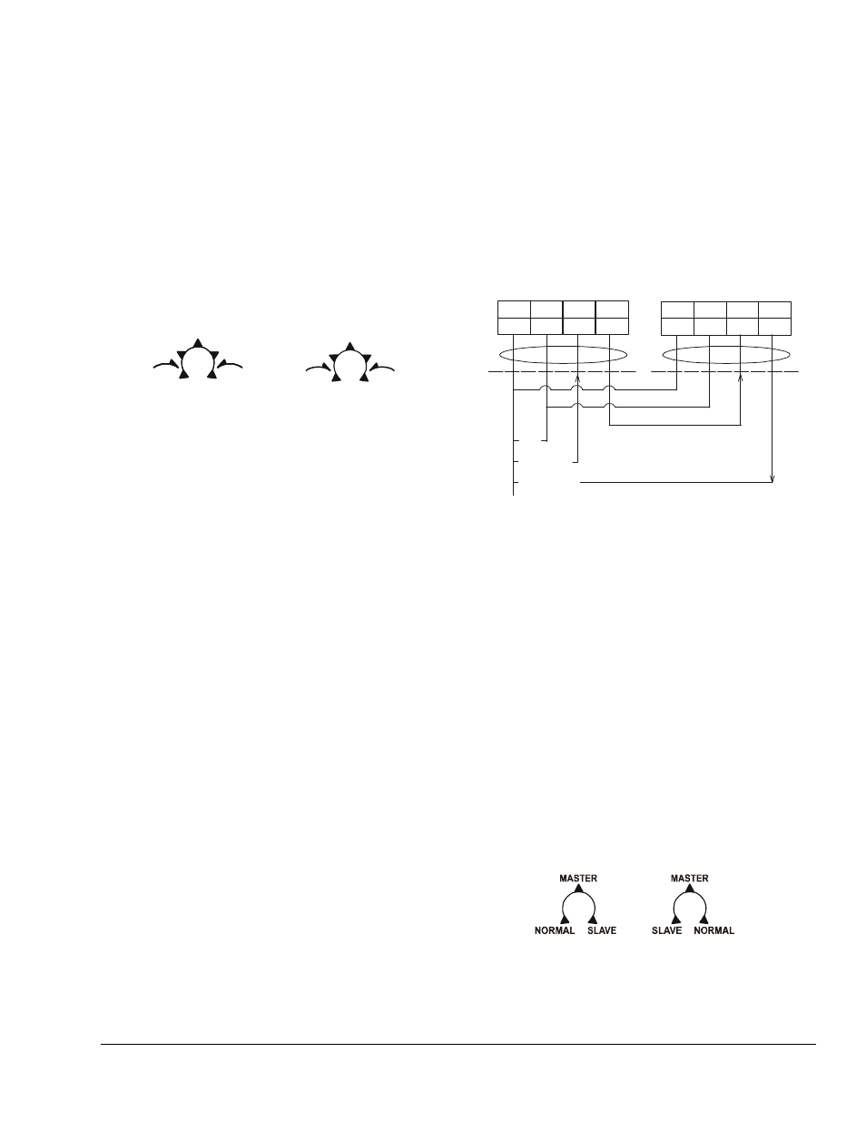
Figure 13: Mode Selection
modes
el
Side A of Actuator
Side B of Actuator
RA
DA
DA
2-10
0-10
0-10
2-10
+
+
CAL
2-10
0-10
0-10
2-10
+
+
CAL
2-10
0-10
0-10
2-10
+
+
CAL
RA
Figure 14: Tandem Connection
F
IG
:t
an
d
em
1
Master
(M9220GGx actuator)
DC 0(2)...10V Control with Tandem Connection
Slave
(
only)
M9220GGx actuator
Y
DC 0(2)...10 V
+
U
+
1
2
3
4
BLK RED GRY ORN
AC/DC
24 v
~(+)
DC 0(2)...10 V
COM
+
1
2
3
4
BLK RED GRY ORN
se
le
c
t
Side A of Actuator
Side B of Actuator
Figure 15: Tandem Selector Switch