Repairs and replacement, Technical specifications, Figure 17 – Johnson Controls M9220-GGX-3 User Manual
Page 11
M9220-GGx-3 Proportional Electric Spring Return Actuators Installation Instructions
11
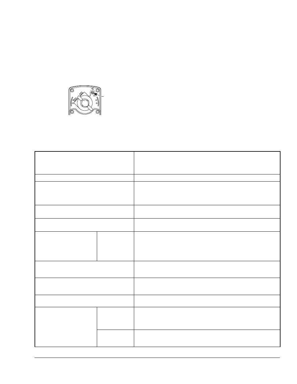
To change the switch point of Auxiliary Switch No. 2,
proceed as follows:
1.
Position the actuator in the full spring return
position.
Note: Auxiliary Switch No. 2 is factory set to trip
when the actuator reaches the 81° position.
2.
Rotate the switch adjuster until it points to the
desired switch point.
3.
Connect Auxiliary Switch No. 2 to a power source
or an ohmmeter, and apply power to the actuator.
The actuator moves to the fully open position and
holds while power is applied.
4.
Observe the switch point. If required, repeat
Steps 2 and 3.
Repairs and Replacement
A number of replacement parts are available; see
Table 1 for more details. If the M9220-GGx-3
Proportional Electric Spring Return Actuator fails to
operate within its specifications, replace the unit. For a
replacement electric actuator, contact the nearest
Johnson Controls® representative.
Technical Specifications
Figure 17: Switch Point Settings
A
FI
G
:s
wp
n
t
Switch
Adjuster
M9220-GGx Proportional Electric Spring Return Actuators (Part 1 of 2)
Power Requirements
AC 24 V (AC 19.2 to 30 V) at 50/60 Hz: Class 2 (North America) or SELV
(Europe), 15.5 VA Running, 7.7 VA Holding Position;
DC 24 V (DC 21.6 to 26.4 V): Class 2 (North America) or SELV
(Europe), 6.7 W Running, 2.9 W Holding Position
Transformer Sizing Requirements
20VA Minimum per Actuator
Input Signal/Adjustment
Factory Set at DC 0 to 10 V, CW Rotation with Signal Increase;
Selectable DC 0 (2) to 10 V or 0 (4) to 20 mA with Field Furnished
500 ohm, 0.25 W minimum resistor;
Switch Selectable Direct or Reverse Action with Signal Increase
Control Input Impedance
Voltage Input: 100,000 ohms;
Current Input: 500 ohms with Field Furnished 500 ohm Resistor
Feedback Signal
DC 0 (2) to 10 V for Desired Rotation Range up to 90°;
Corresponds to Rotation Limits, 1 mA Maximum
Auxiliary Switch Rating
GGC Models
Two Single-Pole, Double-Throw (SPDT), Double-Insulated Switches with
Gold Flash Contacts:
AC 24 V, 50 VA Pilot Duty;
AC 120 V, 5.8 A Resistive, 1/4 hp, 275 VA Pilot Duty;
AC 240 V, 5.0 A Resistive, 1/4 hp, 275 VA Pilot Duty
Spring Return
Direction is Selectable with Mounting Position of Actuator:
Side A, Actuator Face Away from Damper for CCW Spring Return;
Side B, Actuator Face Away from Damper for CW Spring Return
Running and Spring Return Torque
177 lb·in (20 N·m) for a Single Actuator;
354 lb·in (40 N·m) for Two Like Models Mounted in Tandem
531 lb·in (60 N·m) for Three Like Models Mounted in Tandem
Rotation Range
Adjustable from 30 to 90° CW or CCW with Optional
M9220-603 Adjustable Stop Kit; Mechanically Limited to 90°
Rotation Time
Power On
(Running)
150 Seconds for 0 to 177 lb·in (0 to 20 N·m) at All Operating Conditions;
Independent of Load
90 Seconds for 0 to 177 lb·in (0 to 20 N·m) in Calibration Mode or
Override Mode
Power Off
(Spring
Returning)
11 to 15 Seconds for 0 to 177 lb·in (0 to 20 N·m) at Room Temperature;
35 Seconds Maximum for 0 to 177 lb·in (0 to 20 N·m) at -22°F (-30°C)
130 Seconds Maximum for 0 to 177 lb·in (0 to 20 N·m) at -40°F (-40°C)