Installing the switch, Installing the switch into a 19-inch rack, Installing the switch on a wall – IBM 8271 F12 User Manual
Page 2: Powering-up the switch, Setting up for management, Further information
Installing the Switch
DANGER:
SD21-0030.
The User’s Guide also contains further information
on the following steps.
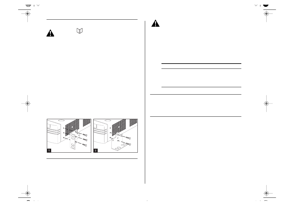
Installing the Switch into a 19-inch Rack
Fit the brackets as shown in Figure 1 (below) to
each side of the unit. Following the manufacturer’s
instructions, secure the unit into the rack.
Installing the Switch on a Wall
Place the Switch the right way up on a hard flat sur-
face, with the front panel facing towards you. Fit
the brackets as shown in Figure 2 (below) to each
side of the unit. Ensure that the wall you are using
is smooth, flat, dry and sturdy. Attach a piece of ply-
wood securely to the wall if necessary. Position the
base of the Switch against the wall, ensuring that
the ventilation holes face sidewards and the front
panel faces upwards. Secure using suitable screws
and fixings (not provided).
Powering-up the Switch
1
Plug the power cord into the power socket at the
rear of the Switch.
2
Plug the other end of the power cord into your
power outlet.
DANGER: It is essential that the mains socket
outlet is installed near to the unit and is accessi-
ble. You can only disconnect the unit by removing
the appliance coupler from the unit.
The Switch powers-up and runs through its Power
On Self Test (POST), which takes approximately 12
seconds. When the POST is complete, check the
Power/Self Test LED to see that your Switch is oper-
ating correctly
Setting Up for Management
For information about setting up the Switch for
management, see Chapter 3 of the User’s Guide.
Further Information
You can find further information about installing
and powering-up the Switch in the IBM 8271 Nways
Ethernet LAN Switch Model F12 and F24 User’s
Guide, Part Number 02L0888.
Color
State
Green
The Switch is powered-up and operating
normally.
Yellow
The Switch has failed its POST.
Off
The Switch is not receiving power.
Part Number: 02L0889
Published: July, 1998
F12_F24i.fm Page 2 Thursday, June 25, 1998 11:47 AM