Nexternal antenna tuners, R warning – Icom IC-718 User Manual
Page 16
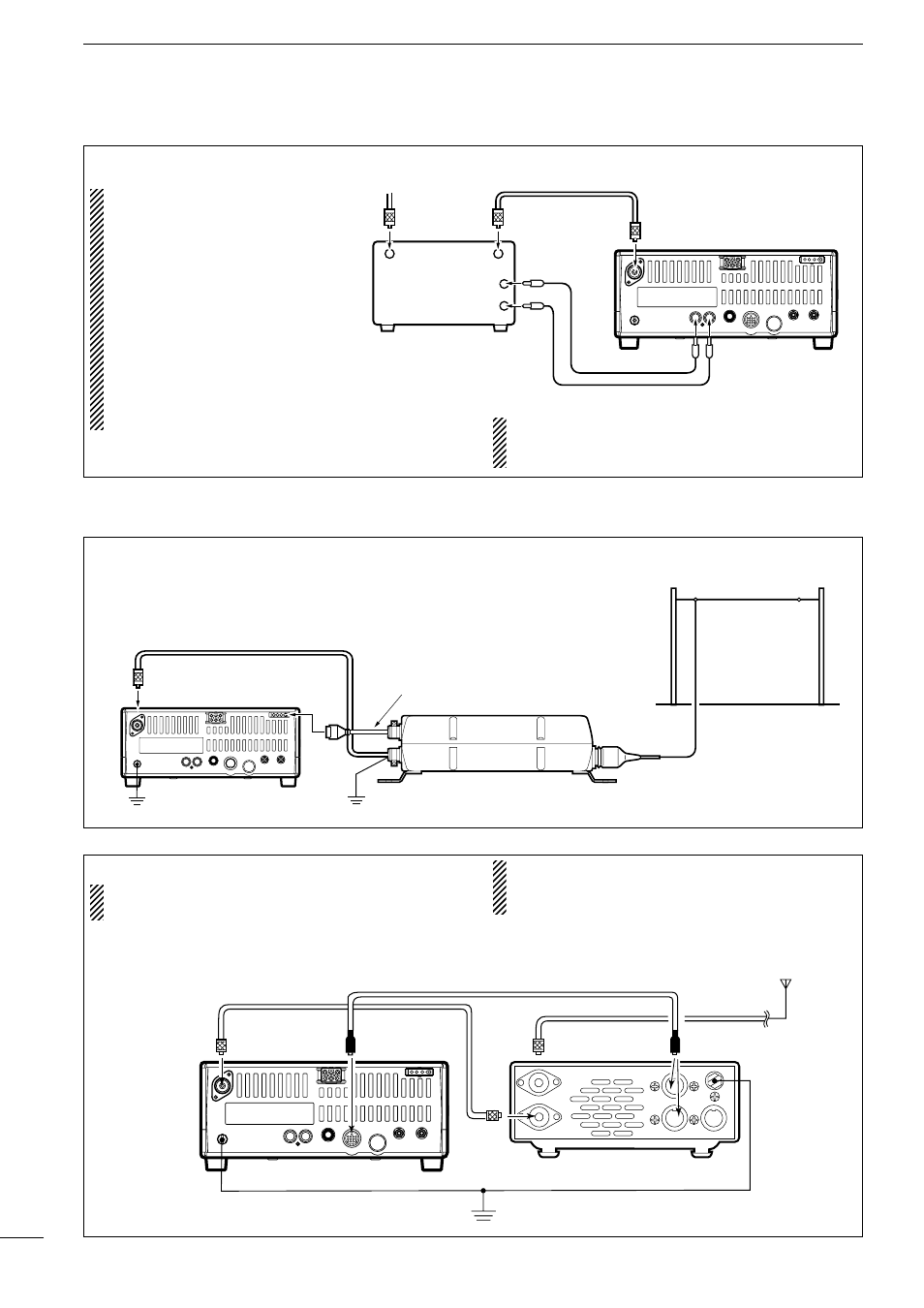
CONNECTING THE AT-180 (p. 28)
DO NOT! connect AT-180 and AH-4 at the same
time. Both tuners will not function correctly.
Turn the IC-718’s power OFF when connecting
the AT-180, otherwise, the CPU may malfunction
and the AT-180 may not function properly.
14
3
INSTALLATION AND CONNECTIONS
n
External antenna tuners
CONNECTING A NON-ICOM LINER AMPLIFIER
R WARNING:
Set the transceiver output
power and linear amplifier
ALC output level referring
t o t h e l i n e a r a m p l i f i e r
instruction manual.
The ALC input level must
be in the range 0 V to –4 V,
and the transceiver does not
accept positive voltage. Non-
matched ALC and RF power
settings could cause a fire or
ruin the linear amplifier.
1 2 3 4
8
7
6
5
9 10 11 12
13
RF OUTPUT
RF INPUT
ALC
SEND
50
Ω coaxial cable
IC-718
ANT
ALC
SEND
To an
antenna
Non-Icom linear amplifier
The specifications for the SEND relay are 16 V
DC 2 A. If this level is exceeded, a large external
relay must be used.
CONNECTING THE AH-4 (p. 29)
Coaxial cable (from the AH-4)
Long wire or optional AH-2b
Ground
IC-718
AH-4
Control cable
Ground
1 2 3 4
8
7
6
5
9 10 11 12
13
Ground
HF
antenna
[ANT]
[ACC]
[ACC]
AT-180
ACC cable supplied with the AT-180
Coaxial cable supplied
with the AT-180
IC-718
one of two
connectors