IMC Networks E1 User Manual
Page 19
16
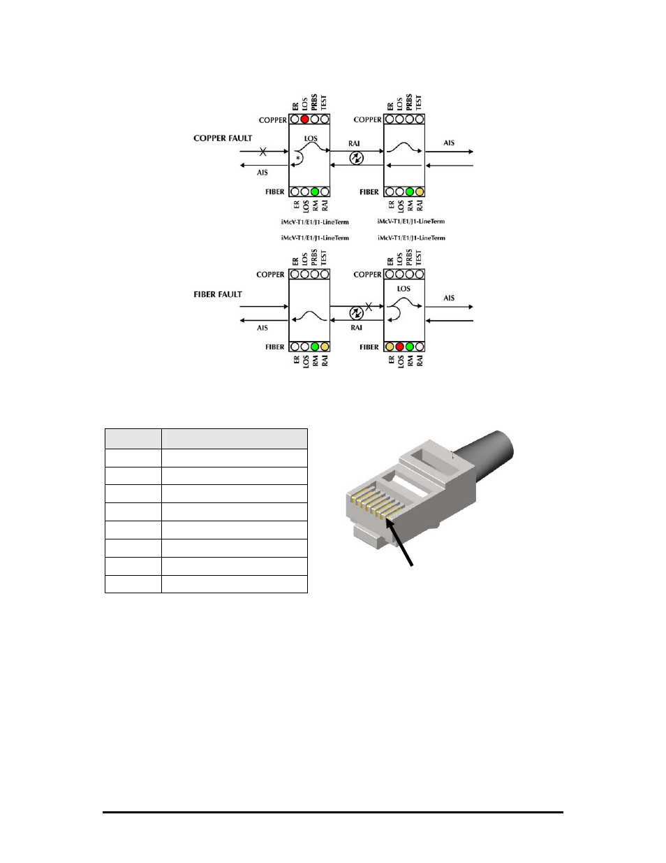
Use the following LED indications to identify the fault location:
*DIP Switch S3-7 must be set to ON for Fault Loopback to operate as illustrated.
The following table lists the pin configuration for the RJ-48 connector.
Pin
Signal
1 Receive
Ring
2 Receive
Tip
3 No
Connection
4 Transmit
Ring
5 Transmit
Tip
6 No
Connection
7 No
Connection
8 No
Connection
Pin 1
This manual is related to the following products: