5 the smart cat5 models, 6 pre-installation guidelines – Minicom Advanced Systems Smart CAT5 User Manual
Page 8
SMART CAT5 SWITCH – 108/116
7
2.5 The Smart CAT5 models
Figure 2 illustrates the front panel of the Smart CAT5 116 model. The 108 model is
the same but with only 8 columns of LEDs.
SELECT
SMART CAT5 SWITCH
10 11 12 13 14 15 16
1
2
3
4
5
6
7
8
9
Selected
CPU on
MINIC
O
M
Figure 2 Smart CAT5 116 front panel
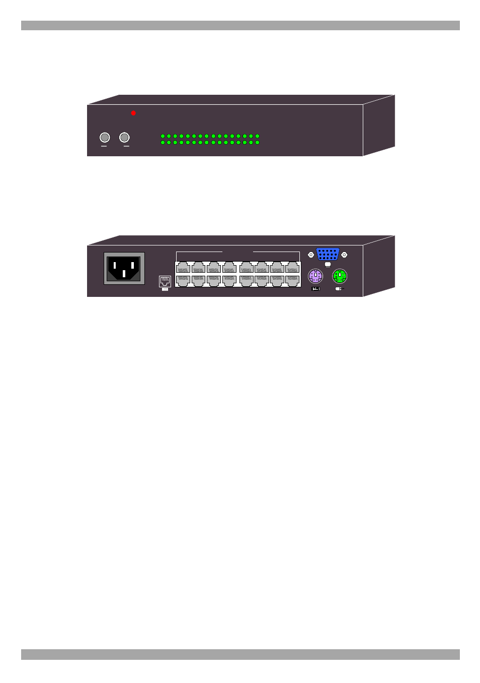
The figure below illustrates the rear panel of the Smart CAT5 116 unit. The 108
model is the same but with only 8 Computer ports.
POWER
100-240 VAC 50/60 Hz
1
2
3
4
5
6
7
8
10
11
12
13
14
15
16
9
COMPUTER
Figure 3 Smart CAT5 116 rear panel
2.6 Pre-installation guidelines
·
Switch off all computers
·
Place cables away from fluorescent lights, air conditioners, and machines that are
likely to generate electrical noise
·
Ensure that the maximum distance between each computer and the Smart CAT5,
does not exceed 10m/33ft