Save these instructions, Symbols, Functional description – Makita 6303H User Manual
Page 4: Assembly
4
SAVE THESE INSTRUCTIONS
WARNING:
MISUSE or failure to follow the safety
rules stated in this instruction manual
may cause serious personal injury.
SYMBOLS
USD201-2
The followings show the symbols used for tool.
V............................volts
A ...........................amperes
Hz..........................hertz
..................alternating current
.......................no load speed
.......................Class II Construction
.../min....................revolutions or reciprocation per
minute
FUNCTIONAL DESCRIPTION
CAUTION:
•
Always be sure that the tool is switched off and
unplugged before adjusting or checking function on
the tool.
Switch action
CAUTION:
•
Before plugging in the tool, always check to see
that the switch trigger actuates properly and returns
to the “OFF” position when released.
•
Switch can be locked in “ON” position for ease of
operator comfort during extended use. Apply
caution when locking tool in “ON” position and
maintain firm grasp on tool.
To start the tool, simply pull the switch trigger. Tool speed
is increased by increasing pressure on the switch trigger.
Release the switch trigger to stop.
For continuous operation, pull the switch trigger and then
push in the lock button.
To stop the tool from the locked position, pull the switch
trigger fully, then release it.
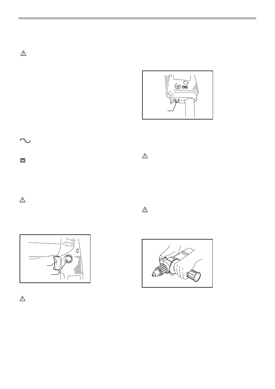
Reversing switch action
This tool has a reversing switch to change the direction of
rotation. Move the reversing switch lever to the “FWD”
position for clockwise rotation or the “REV” position for
counterclockwise rotation.
CAUTION:
•
Always check the direction of rotation before
operation.
•
Use the reversing switch only after the tool comes
to a complete stop. Changing the direction of
rotation before the tool stops may damage the tool.
ASSEMBLY
CAUTION:
•
Always be sure that the tool is switched off and
unplugged before carrying out any work on the tool.
Installing side grip (auxiliary handle)
Always use the side grip to ensure operating safety.
Install the side grip so that the teeth on the grip fit in
between the protrusions on the tool barrel.
Then tighten the grip by turning clockwise at the desired
position. It may be swung 360° so as to be secured at
any position.
1. Switch trigger
2. Lock button
n
˚
1
2
003013
1. Reversing
switch lever
1
003023
003037