Multiquip AC Generator GA-6HA User Manual
Page 2
© COPYRIGHT 2005, MULTIQUIP INC.
Montreal, Canada • Manchester, UK
Rio De Janeiro, Brazil • Cipsa, Mexico
MULTIQUIP INC.
POST OFFICE BOX 6254 • CARSON, CA 90749
310-537-3700 • 800-421-1244 • FAX: 310-537-3927
E-MAIL: [email protected] • WWW: multiquip.com
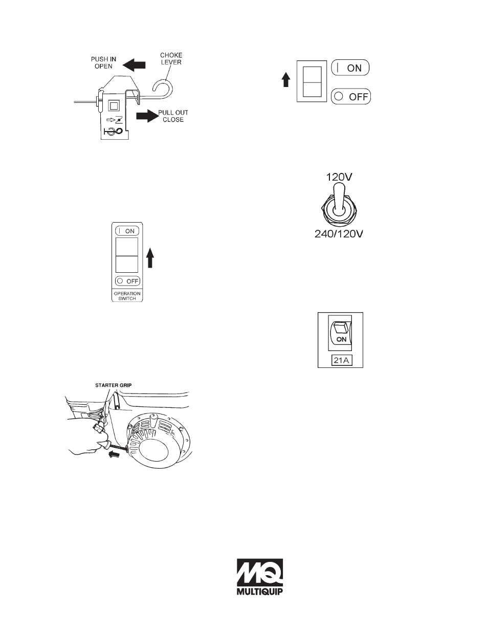
Figure 5. Choke Lever
5. Grasp the starter grip (Figure 7) and slowly pull it out.
The resistance becomes the hardest at a certain
position, corresponding to the compression point. Pull
the starter grip briskly and smoothly for starting.
Figure 7. Starter Grip
2. Place the
choke lever (Figure 5) in the CLOSED
position if starting a
cold engine.
3. Place the
choke lever (Figure 5) in the OPEN position
if starting a
warm engine or the temperature is
warm.
4. Place the
generator ON/OFF switch (Figure 6) in the
ON position.
Figure 6. Generator On/Off Switch
6. If the engine has started, slowly return the choke lever
(Figure 5) to the
OPEN position. If the engine has not
started, repeat steps 1 through 5.
7. Before the generator is placed into operation, run the
engine for 3-5 minutes. Check for abnormal smells,
fuel leaks, and noises that would associate with loose
components.
Figure 8. Idle Control Switch
Connecting the Load
1. Place the full power switch (Figure 9) in the 120V or
240/120V position depending on application.
Figure 9. Power Switch
2. If small wattage power tools are required, connect
them to the 60 Hz output receptacles at this time.
Stopping the Engine
1. Place the main circuit breaker (Figure 3) in the OFF
position.
2. Place the
idle control switch (Figure 8) in the OFF
position.
3. Let the engine run at idle with no load for 2-3 minutes.
4. To shut down the engine, place the generator ON/OFF
switch (Figure 6) in the OFF position.
5. Place the engine
fuel valve lever (Figure 4) to the
"OFF" position.
6. Remove the
load from the generator.
8.
Place the idle control switch (Figure 8) in the ON
(up) position.
Figure 10. Main Circuit Breaker (ON)
3. Place main circuit breaker (Figure 10) in the ON
position.