House fan – Monte Carlo Fan Company 5CY60XX User Manual
Page 3
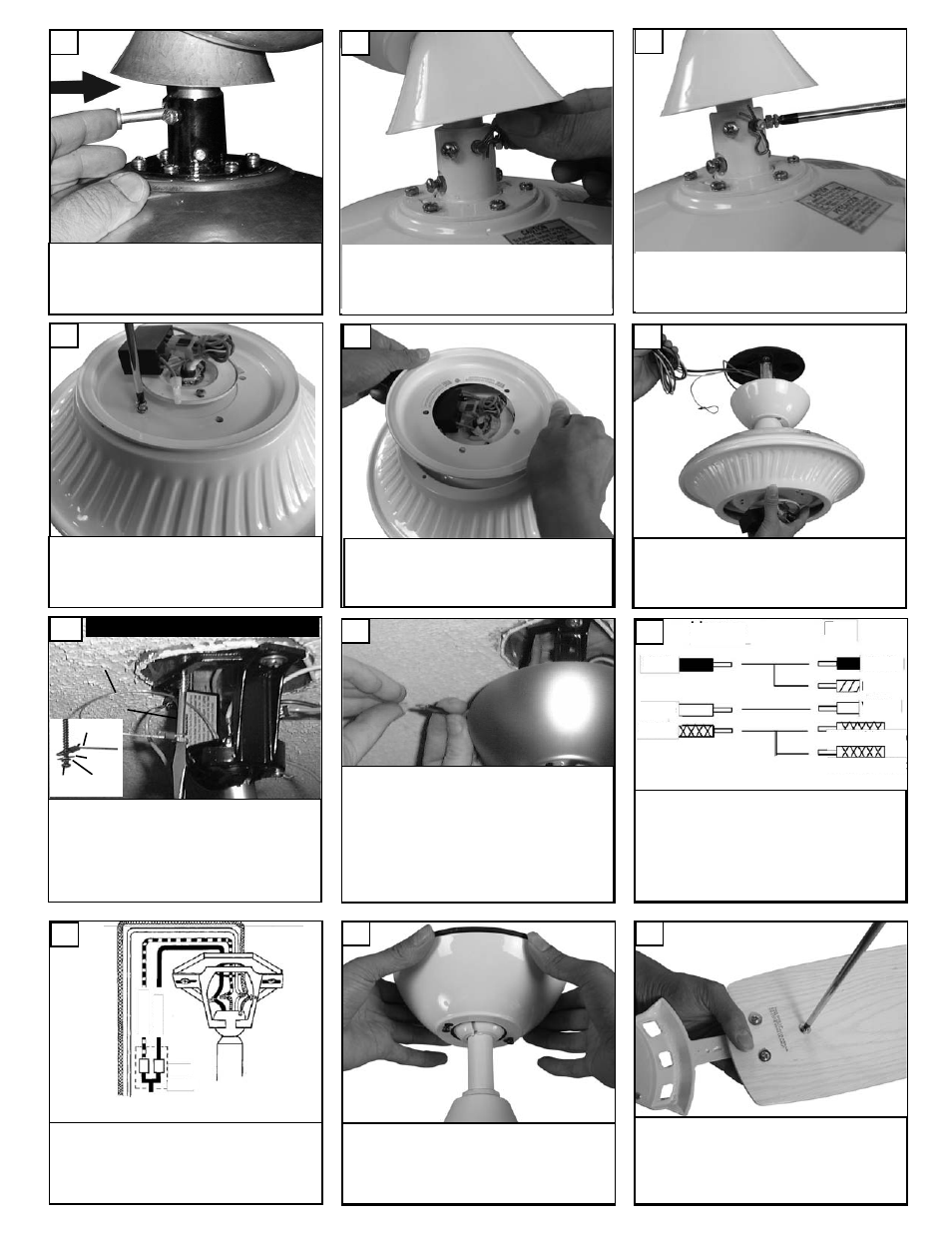
Insert downrod into motor yoke.
Next, insert clevis pin through yoke
and downrod.
Carefully lift fan assembly onto mounting
bracket. Rotate fan so that the notch on the
ball engages the ridge in the mounting bracket.
This will allow hands-free wiring.
12
7
9
Install 3 screws and washers per
blade and tighten securely. Repeat
for all 5 blades. The blades will have
a label showing this side up on each
blade.
18
Make wire connections to power source
using wire nuts provided. Make sure that
no filiments are outside of the wirenut.
After making the wire connections, the
wires should be spread apart with the
grounded conductor and the equipment-
grounding conductor on one side of the out-
let box and ungrounded conductor on the
other side of the outlet box.
14
For pullchain controls, follow diagram above.
Make sure that all exposed wiring is secured
inside wire nuts. Note: Wires from house may
vary in color and may not include ground wire.
After wiring is conplete, gently push wires into
junction box with wire nuts pointing upward.
Refer to point 3 of safety tips.
15
House
Fan
Black
White
Green
Black
White
Green(downrod)
Green(Bracket)
Blue
For control of fan and optional light from wall
location, follow diagram above. NOTE: A profes-
sional electrician is recommended for this type
of installation.
16
Raise the canopy up and align the
two holes in the canopy with the two
holes in the hanger bracket. Secure
with two screws provided.
17
Tighten both yoke set screws to fur-
ther secure downrod.
Li
gh
t
Sw
it
ch
Fa
n
Sw
it
ch
Wall
Control
8
Secure with cotter pin.
Remove screws from stabilizer plate
on bottom of fan motor.
10
11
Remove stabilizer plate you will not
need this plate.
For Canadian installation and for USA fan and
light kit combinations over 35 lbs, in both flush
and downrod mode the safety cable must be
installed into the house structure beams using
the 3” lag screws,washers, and lock washers.
provided. Make sure that when the safety cable
is fully extended the leadwires are longer than
the cable and no stress is placed on the lead-
wires.
13
Safety cable installation
Safety Cable
Lag Screw
safety
cable
3” lag
screw
lock
washer
washer