4 power-on and checkout, Power-on and checkout, Table 5-3. power-on and checkout procedure – Multi-Tech Systems DataTalker DT101/xx User Manual
Page 61: 61 chapter 5 - installation
61
Chapter 5 - Installation
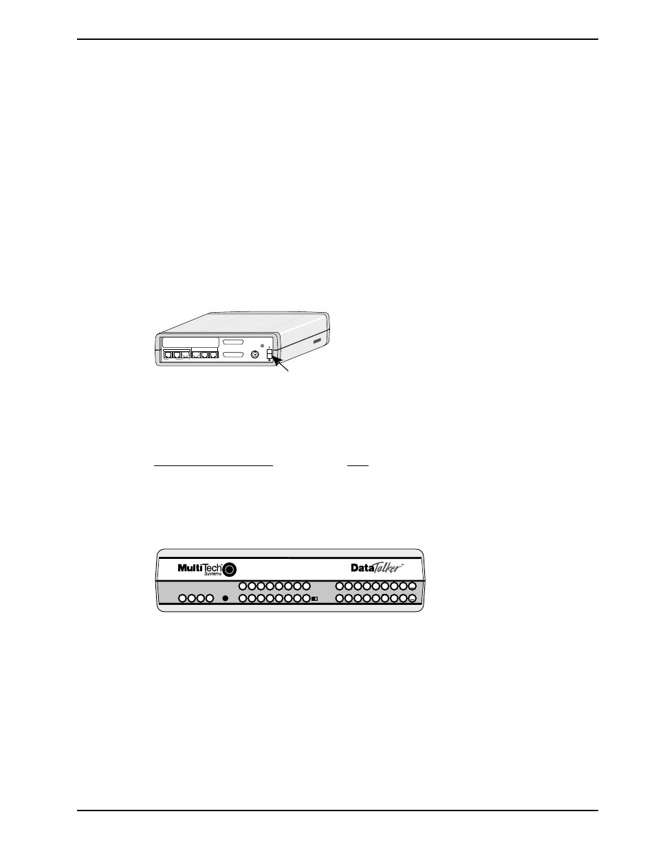
5.4 Power-On and Checkout
The desktop and rack-mounted versions of the DataTalker differ in how power is applied. The
desktop version has a power switch that you must turn on. The rack version has no power
switch; you apply power by inserting it into a powered-up rack. It is always on as long as the rack
is powered up.
Table 5-3. Power-On and Checkout Procedure
Step
Procedure
1
Desktop version: Ensure that the power supply is connected to the unit’s power connector
and an AC outlet.
Rack version: Ensure that the DataTalker is properly seated in a RackTalker rack. Tighten the
front panel screws to ensure a good connection with the RackTalker power bus.
2
Desktop version: Apply power (press the power switch on the back of the unit to I [on]).
Rack version: Plug the RackTalker rack into an AC outlet, if it is not already powered up.
MODEM
DSU/TA
DIAL-UP
LEASED
DIGITAL
VOICE/FAX CHANNEL 1
FXO
FXS
EXTERNAL COMPOSITE
DATA/COMMAND
RS232C/V.35
E&M
INTERNAL COMPOSITE
POWER
GND
Power
Switch
Figure 5-13. Power Switch (Desktop Version)
3
Verify the states of the following composite link LEDs. The LED should be on for each
installed feature and off for each uninstalled feature:
Composite Link Device
LED
Internal 28.8K bps modem
MDM
Internal 56K DSU
DSU
Internal ISDN terminal adapter
TA
External modem, DSU, or TA
EXT
External V.35 interface
V35
COMPOSITE
LINK
STATUS
VOICE /
FAX 1
DATA/
COMMAND
ORIG
101 MDM/TA
RXT
FCR
RD
TM
V35
EXT
MDM
DSU
CD
RCV
XMT
CTS
56
RTS
NS
OOS
28.8
OH
DBUP
TA
DTR
2B
FXS
FXO
E&M
FAX
XMT
RCV
XSG
RSG
COM
XMT
RCV
FC
VOICE /
FAX 2
RSG
XSG
RCV
XMT
FAX
E&M
FXO
FXS
Data / Voice / Fax Concentrator
Figure 5-14. Front Panel
4
Establish a link with the remote DataTalker if the local DataTalker is not configured to link
automatically.
5
Verify that the composite link is communicating with the remote DataTalker. The RD LED
should be off. The following LEDS should be on:
Terminal adapter:
CD, RCV, XMT, CTS, DTR, and 2B (if so configured)
Modem:
CD, RCV, XMT, CTS, and DTR
DSU:
CD, RCV, XMT, CTS, and RTS