McIntosh MC352 User Manual
Page 7
7
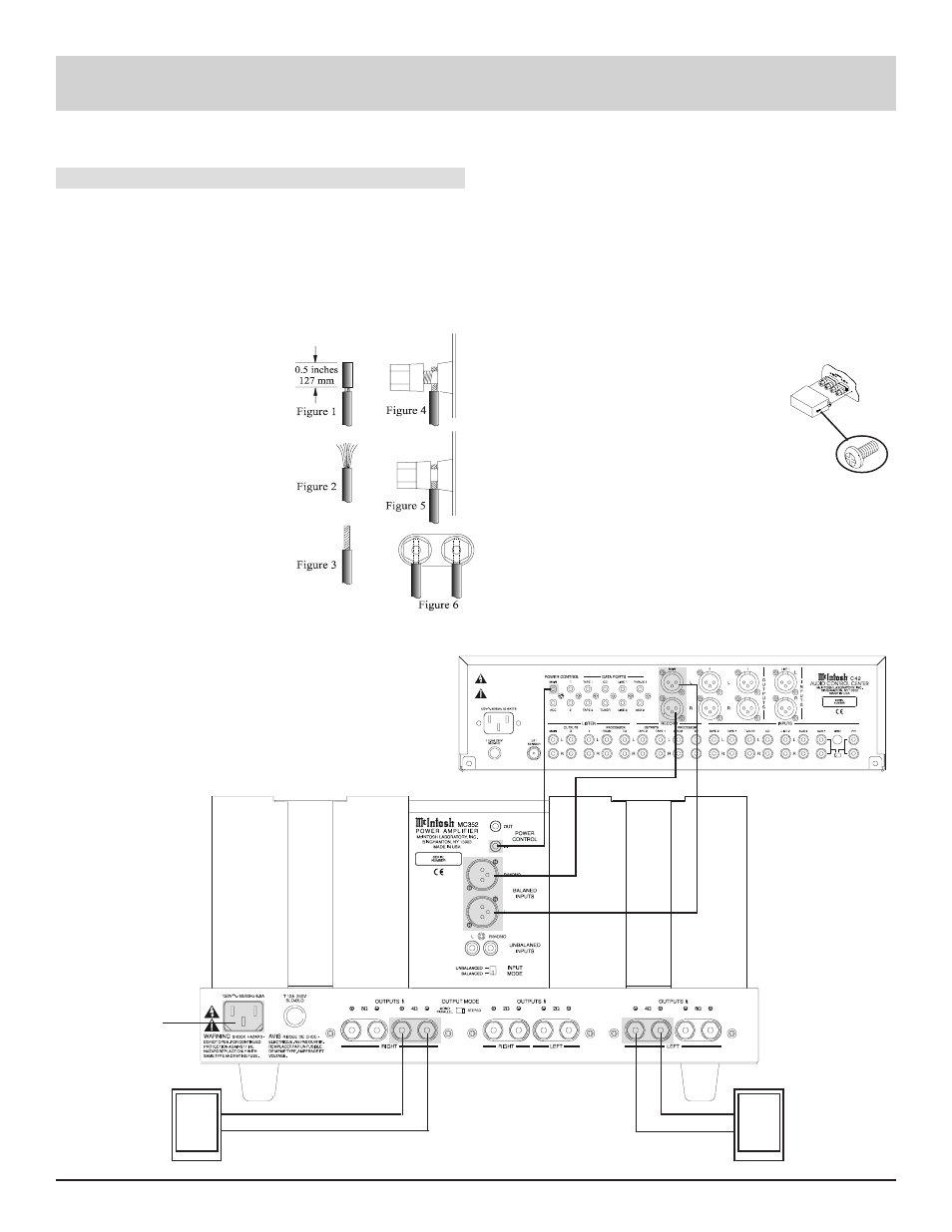
McIntosh C42 Audio Control Center
How to Connect the MC352
1. Connect the MC352 power cord to a live AC outlet.
2. Connect a power control cable from the control center
Power Control Out to the MC352 Power Control In.
3. Prepare the loudspeaker hookup cables as follows:
A. Carefully remove sufficient insulation from the
loudspeaker cable ends to just fit within the bind-
ing post with no exposed
wire accessible. Refer to
figure 1.
B. If the cable is stranded,
carefully twist the strands
together as tightly as pos-
sible. Refer to figures 2
& 3.
Note: If desired, the
twisted cable section
can be tinned with a
solder iron to keep
the strands together
and/or attach
appropriate
connector ends.
C. Insert the bare section of the cable end or connec-
tor into the access hole, and tighten the terminal
nut clockwise until the cable is firmly clamped
into the terminal so the wires cannot slip out. Re-
fer to figure 4.
D. Insert the bare section of the cable end or connec-
tor into the access hole, and tighten the terminal
nut clockwise until the cable is firmly clamped
How to Connect the MC352
into the terminal. Refer to figures 5 & 6.
Note: The bare sections of the cable ends or the non
insulated part of the connectors must not be exposed on
either side of the terminal access hole.
E. Repeats Steps A through D for each speaker cable
used with the amplifier.
4. Connect the loudspeaker cables to the appropriate termi-
nals for your loudspeakers, being careful to observe the
correct polarities. Output impedance connections of 2
ohms, 4 ohms and 8 ohms are provided.
If the impedance of your loudspeakers
is rated at other than the listed imped-
ance connections, use the nearest lower
connection.
5. Install the plastic protective loudspeaker
terminal covers that were supplied with
your amplifier. Refer to figure 7.
6. Connect a cable from the balanced outputs of a control
center to the MC352 balanced Input connectors for both
audio channels and power control.
Note: An optional hookup is to use unbalanced cables from a
McIntosh Control Center to Unbalanced Inputs of the
MC352.
To AC Outlet
123456789
123456789
123456789
123456789
123456789
123456789
123456789
123456789
123456789
123456789
123456789
123456789
123456789
123456789
123456789
123456789
123456789
123456789
123456789
123456789
123456789
123456789
123456789
123456789
Right Loudspeaker
4ohm
Left Loudspeaker
4ohm
Figure 7