G32msw on the a25cw, Iso 9001 – Moffat A25CW User Manual
Page 2
In line with policy to continually develop and improve its products, Moffat Limited reserves the right to change specifications and design without notice.
Printed in New Zealand
© Copyright Moffat Ltd
Moffat/5244-G32MSW/A25CW/BH/2M/09.06
U.S.A
Moffat Inc
3765 Champion Boulevard
Winston-Salem
North Carolina 27105
Call Free 1800 551 8795
Ph 336-661 0257
Fax 336-661 9546
Email [email protected]
www.moffat.com
Canada
Serve Canada
22 Ashwarren Road
Downview
Ontario, M3J 1Z5
Ph 416-631 0601
Fax 416-631 0315
Email [email protected]
Australia
Moffat Pty Limited
740 Springvale Rd
Mulgrave
Victoria 3170
Australia
Ph 03-9518 3888
Fax 03-9518 3833
Email [email protected]
www.moffat.com.au
New Zealand
Moffat Limited
16 Osborne St
PO Box 10-001
Christchurch
New Zealand
Ph 03-389 1007
Fax 03-389 1276
Email [email protected]
www.moffat.co.nz
United Kingdom
Blue Seal Limited
Units 6-7 Mount St
Business Park
Birmingham B7 5QU
England
Ph 0121-327 5575
Fax 0121-327 9711
Email [email protected]
www.blue-seal.co.uk
www.moffat.com
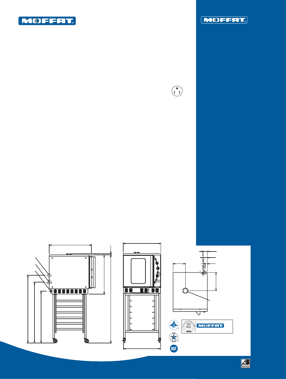
G32MSW shown on optional A25CW stand
Designed and manufactured by
QUALITY
MANAGEMENT STANDARD
ISO 9001
ISO 9001
All Turbofan products are designed and manufactured
by Moffat Ltd using the internationally recognised
ISO 9001 quality management system, covering
design, manufacture and final inspection, ensuring
consistent high quality at all times.
C O N S T R U C T I O N ( G 3 2 )
Stainless steel top and sides
Enamel oven interior
Field reversible door
Toughened twin pane door window glass
Full stainless steel door handle
4 pan capacity (4 wire oven racks included)
Fully insulated
Fully enclosed motor
C O N S T R U C T I O N ( A 2 5 )
Stainless steel frame and rack supports
Strong robust and functional
Casters
Supplied knocked down for assembly on site
C O N T R O L S
On/off switch
Mechanical thermostat,
variable between 150
°
F to 600
°
F
1 hour bake timer with buzzer
3 hour roast timer
Cook n hold factory preset at 158
°
F
(range 140
°
F to 194
°
F)
Water injection steam (momentary switch)
Low velocity fan system
2 oven lights
Infra-red burner system
C L E A N I N G A N D S E R V I C I N G
Easy clean stainless steel and enamel surfaces
Fully removable racks and baffle
Access to all controls from front panel
Full access side service panel
Removable door seals
O P T I O N S
Cookie Kit
E89 Proofer and Holding Cabinet
Double stacking kit
Full range of 18" x 26" pans
Chicken racks
S P E C I F I C AT I O N S
Gas Rating
35 MJ/hr, 33,000 Btu/hr
Gas Inlet
1
/
2
” female NPT
Electrical requirements
110-120V, 60Hz, 0.24kW, 1P+N+GND
Nema 5-15P cordset fitted
Water
3
/
4
” thread
80psi max inlet pressure
20psi min inlet pressure
External Dimensions
Width
28”
(710mm)
Height
66
1/2
” (1689mm on stand)
35
1/2
” (900mm on feet)
Depth 32”
(810mm)
Internal Dimensions (G32)
Width
18”
(460mm)
Height
20
1/2
” (520mm)
Depth
26”
(660mm)
Oven Rack Dimensions
Width
18”
(460mm)
Depth
26”
(660mm)
Between racks
5” (125mm)
3” (75mm) with cookie kit
Nett Weight (total)
287lbs
(130kg)
Packing Data (G32)
353lbs
(160kg)
23ft
3
(0.65m
3
)
Width 29
1/2
” (750mm)
Height 36
1/2
” (925mm)
Depth 37
1/4
” (945mm)
Packing Data (A25)
42lbs (19kg)
3.2ft
3
(0.09m
3
)
Width
28
3/8
” (720mm)
Height
35
1/2
” (900mm)
Depth
5
3/4
” (145mm)
Clearances
Left side 3”
(75mm)
Right side3”
(75mm)*
Rear
3”
(75mm)
Top
8”
(200mm)
GAS
1E
MWS
GAS
E
1
MWS
GAS ENTRY
ELECTRICAL ENTRY
WATER ENTRY
E
1
MWS
FLUE VENT
3
5
/
8
"
(92mm)
28"
(710mm)
32"
(810mm)
2"
(50mm)
3"
(76mm)
39"
(990mm)
45
3
/
4
"
(1162mm)
DOOR SWING
21
3
/
4
"
(550mm)
10"
(255mm)
15"
(380mm)
29
1
/
2
"
(750mm)
66
1
/
2
"
(1689mm)
51"
(1295mm)
27
1
/
2
"
(702mm)
Note: NSF certification applies to ovens only.
1"
(25mm)
G32MSW on the A25CW
Gas Convection Oven on an optional
Stainless Steel Stand
*Fixed installations require
at least 500mm(20”)
clearance at RHS for
serviceability.