English – Middleby Marshall Gas Oven PS536GS User Manual
Page 15
15
ENGLISH
SECTION 2 - INSTALLATION
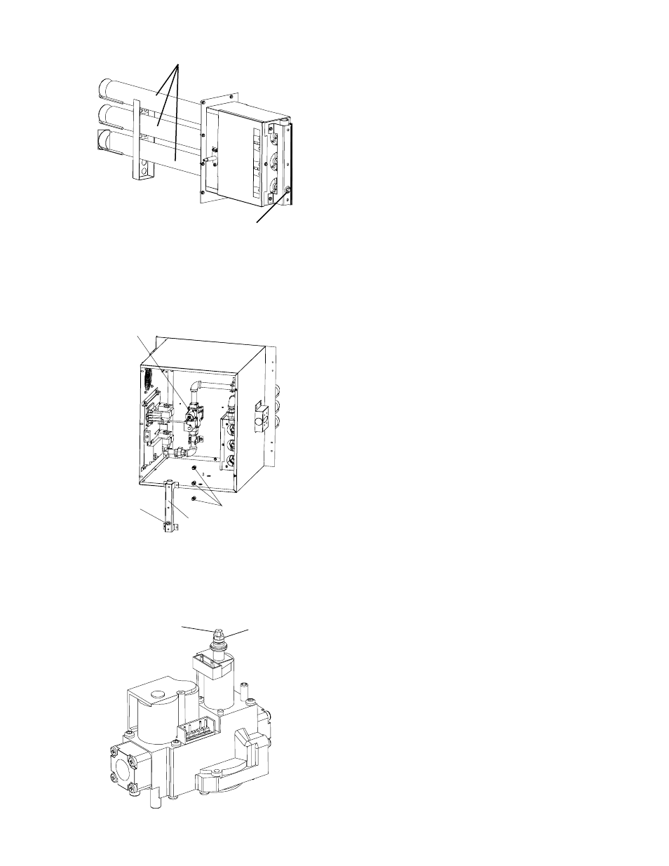
Gas
Valve
Main•
Pressure•
Tap
Gas Burner
Assembly
Main•
Orifices
Figure 2-16. Gas Burner Assembly
Gas Burner
Manifold Pressure Tap
Adjustment Screw (5 mm)
for minimum pressure
setting
Adjustment Screw
(8 mm) for
maximum
pressure
setting
Figure 2-17. Burner Assembly
Figure 2-18. Gas Valve
5.
Disconnect electrical connection of the Moduplus
®
.
6.
Check minimum pressure setting and readjust if
necessary. (See Adjusting Minimum Pressure Setting for
proper adjusting procedure.)
7.
Reconnect pressure feedback connection (if appcable).
8.
If minimum and maximum pressures are set, wire the
Moduplus
®
in circuit.
9. Close pressure tap screw.
F.
Adjusting the Minimum Pressure Setting
1.
Disconnect pressure feedback connection (if appcable).
2.
Connect a suitable pressure gauge to pipe line or to outlet
pressure tap of gas control concerned, to measure burner
pressure (measuring point must be as near to burner as
possible).
3.
Disconnect electrical connection of the Moduplus
®
.
4.
Energize operator, set control in operation and wait until an
outlet pressure is recorded on pressure gauge.
5.
If minimum rate pressure needs adjustment, use an 8 mm
wrench to turn adjustment screw for minimum pressure
setting (clockwise to increase or counter-clockwise to
decrease pressure), until the desired minimum outlet
pressure is obtained.
6.
Check if main burner lights easily and reliable at minimum
pressure.
7.
Reconnect pressure feedback connection (if appcable).
8.
Close pressure tap screw.
G.
Checkout
After any adjustment, set appliance in operation and observe
through a component cycle to ensure that burner system com-
ponents function correctly.
H.
Maintenance
It is recommended to check yearly the minimum and the
maximum setting and readjust them if necessary.