Ccaannaaddiiaann m moouunnttiinngg oonnllyy, House fan – Monte Carlo Fan Company 5STR52 User Manual
Page 4
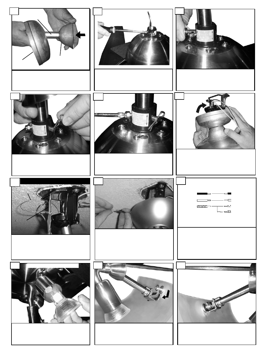
Tighten both yoke set screws to further secure down-
rod.
23
Install cotter pin into cross pin to secure.
22
Align holes in downrod and holes in yoke and install
cross pin.
21
Loosen the 2 yoke screws.
20
Make wire connections as per above diagram.
Connect the white wire from the fan to the
White or Neutral wire from the power source.
Connect the black wire from the fan to the
Black or hot wire from the power source.
Connect all Green / Yellow wires from the fan,
Downrod and mounting bracket to the Ground
wire from the house.
27
For Canadian installation in both flush and
downrod mode the safety cable must be
installed into the house structure beams using
the 3” lag screws provided. Make sure that
when the safety cable is fully extended the
leadwires are longer than the cable and no
stress is placed on the leadwires.
25
CCaannaaddiiaann m
moouunnttiinngg oonnllyy
Safety Cable
Lag Screw
Make wire connections to power source using
wire nuts provided. Make sure that no filiments
are outside of the wirenut. After making the
wire connections, the wires should be spread
apart with the grounded conductor and the
equipment-grounding conductor on one side of
the outlet box and ungrounded conductor on
the other side of the outlet box.
26
House
Fan
Black
White
Green
Black
White
Green(downrod)
Green(Bracket)
When alligned push screw in glass into the slotted
arm from light kit.
30
Use caution with the sloted fitter arms, do not
force the fitter arms. Align the 3 sloted arms with
the 3 screws in glass.
29
Plug in the 3 light bulbs by aligning the 2
prongs on bulb with holes in socket and then
push in and twist the 50 watt bulbs which are
GU10.
28
Use caution when hanging fan not to hold by blades
are put any pressure on blades or blade arms. This
could create problems of blade pitch deviation,
deforming blade arms, or scratching of
blades.Carefully lift fan assembly by fan body onto
mounting bracket. Rotate fan so that the notch on the ball
engages the ridge in the mounting bracket. This will allow
hands-free wiring.
24
PEFORM FOR LIGHT KIT IF USED
Thread wires and safety cable from fan
through yoke cover, canopy and downrod.
19
downrod
canopy
yoke cover