Warning, Maintenance and repair instructions, Lt31cs – MTD LT31CS User Manual
Page 24
24
MAINTENANCE AND REPAIR INSTRUCTIONS
Fig. 55
Fig. 54
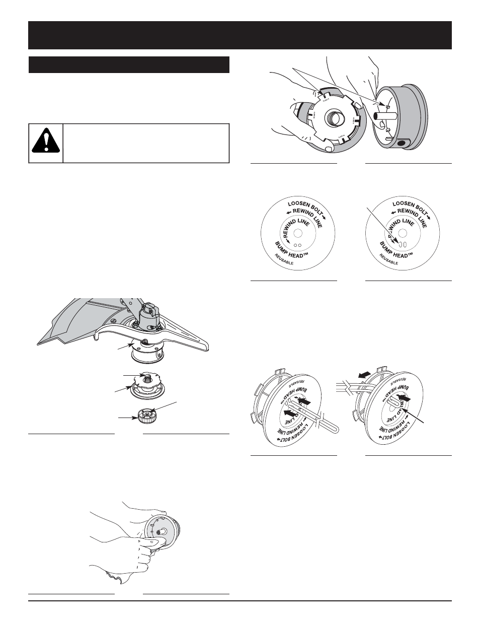
NOTE: SplitLine™ can only be used with the inner reel
with the slotted holes. Single line can be used on
either type of inner reel. Use Figure 54 to identify
the inner reel you have.
NOTE: Always use the correct line length when installing
trimming line on the unit. The line may not release
properly if the line is too long.
Single Line Installation
Go To Step 8 for SplitLine™ Installation
6. Take approximately 5 m (16 feet) of new trimming
line, loop it into two equal lengths. Insert each end of
the line through one of the two holes in the inner reel
(Fig. 55). Pull the line through the inner reel so that
the loop is as small as possible.
7. Wind the lines in tight even layers, onto the reel
(Fig. 56). Wind the line in the direction indicated on
the inner reel. Place your index finger between the
two lines to stop the lines from overlapping. Do not
overlap the ends of the line. Proceed to step 11.
Slotted
Holes
For Use with SplitLine™
or Single Line
For Use with Single
Line ONLY
Loop
Indexing Teeth
Fig. 53
This section covers both SplitLine™ and standard single
line installation.
Always use original equipment manufacturer 2.41 mm
(0.095 in) replacement line. Line other than the specified
may make the engine overheat or fail.
There are two methods to replace the trimming line:
• Wind the inner reel with new line
• Install a prewound inner reel
Winding the Existing Inner Reel
1. Hold the outer spool with one hand and unscrew the
Bump Knob clockwise (Fig. 51). Inspect the bolt inside
the bump knob to make sure it moves freely. Replace
the bump knob if damaged.
2. Remove the inner reel from the outer spool (Fig. 51).
3. Remove spring from the inner reel (Fig. 51).
4. Use a clean cloth to clean the the inner reel, spring,
shaft and inner surface of the outer spool (Fig. 52).
5. Check the indexing teeth on the inner reel and outer
spool for wear (Fig. 53). If necessary, remove burrs or
replace the reel and spool.
Inner Reel
Spring
Outer Spool
Bump Knob
Bolt
Fig. 51
LT31CS
LINE INSTALLATION: BUMP HEAD
Never use metal-
reinforced line, wire,
chain or rope. These can break off and
become dangerous projectiles.
WARNING:
Fig. 52