Assembly instructions, Lt31cs, Lt31 – MTD LT31CS User Manual
Page 10: Lt31c
10
ASSEMBLY INSTRUCTIONS
LT31CS:
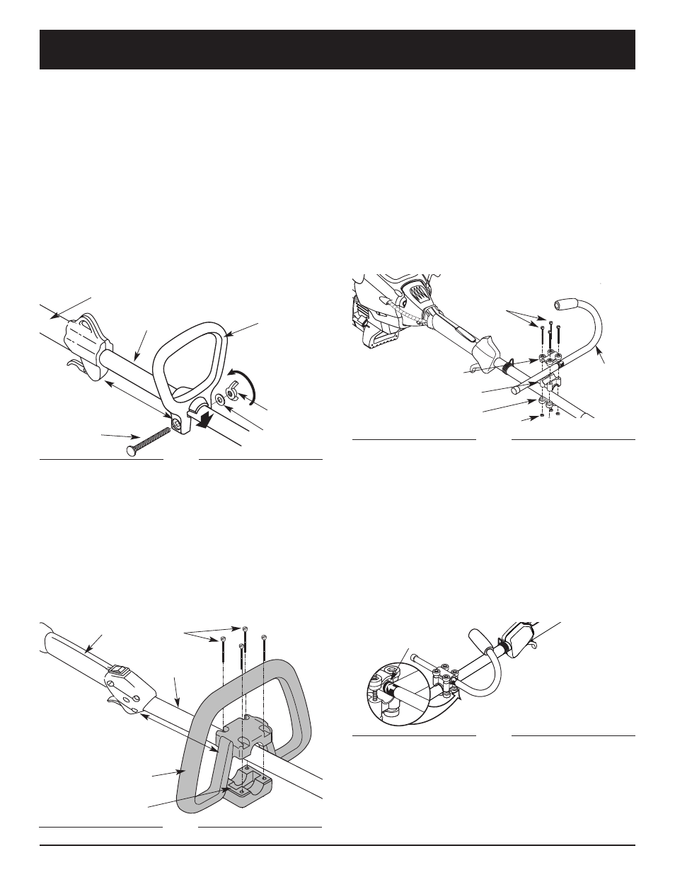
J-handle
1. Place the J-handle between the top and middle
clamp pieces (Fig. 3).
(4) Screws
Top Clamp
J-Handle
Middle Clamp
Bottom Clamp
Nuts
2. While holding the three pieces together, install the four
(4) screws through the top clamp and into middle clamp.
NOTE: The holes in the top and middle clamp will line up
only when assembled correctly.
3. Place the clamps and the J-handle over the shaft
housing and onto the bottom clamp.
4. Hold each hex nut in the bottom clamp recess with a
finger. Start screws with a large Phillips screwdriver.
Do not tighten until you make the handle adjustment.
5. Slide the J-handle in or out until the arrow/white line on
the decal touches the clamp assembly (Fig. 4). You must
first loosen the screws if the handle is pre-installed.
Fig. 3
Fig. 4
6. While holding the unit in the operating position (Fig.
27), position the J-handle to the location that provides
you the best grip.
7. Tighten the clamp screws evenly, until the J-handle
is secure.
Decal
INSTALL AND ADJUST THE HANDLE
Use the following information to install or adjust the
handle onto your trimmer. Follow the instructions that
apply to your type of handle.
LT31:
Small D-handle
1. Push the D-handle down onto the shaft housing so
that the handle slants towards the shaft grip (Fig. 1).
The squared bolt hole in the handle is to the right.
2. Insert the shoulder bolt into the squared hole in the
handle and push through. On the left side of the
handle, place the washer on the bolt, then screw the
wing nut onto the bolt. Do not tighten until you make
the handle adjustment.
3. Rotate the D-handle to place the grip above the top
of the shaft housing. Place it a minimum of 15.24 cm
(6 inches) from the end of the shaft grip.
4. While holding the unit in the operating position
(Fig. 27), position the D-handle to the location that
provides you the best grip.
5. Tighten the wing nut until the D-handle is secure.
Fig. 1
Bolt
Washer
Wing Nut
Tighten
Shaft Grip
D-Handle
Minimum 6 inches
(15.24 cm)
Shaft Housing
LT31C:
Large D-handle
1. Remove the screws and bottom clamp piece that
were installed on the D-handle for shipping.
2. Place D-handle the over the shaft housing and onto
the bottom clamp (Fig. 2). Place it a minimum of
15.24 cm (6 inches) from the end of the shaft grip.
(4) Screws
Shaft
Housing
D-Handle
Bottom Clamp
Shaft Grip
Minimum 6 inches
(15.24 cm)
Fig. 2
3. Start screws with a large Flat-head or T-25 Torx
screwdriver. Do not tighten until you make the
handle adjustment.
4. If the D-handle was pre-installed, loosen the screws
on the handle just enough to move it.
5. While holding the unit in the operating position
(Fig. 27), maneuver the D-handle to the location that
provides you the best grip.
6. Tighten the clamp screws evenly, until the D-handle
is secure.