Step 6. wiring - optional forced air blower kit – Maxon Telecom MPB3328CNE User Manual
Page 9
NOTE: DIAGRAMS & ILLUSTRATIONS NOT TO SCALE.
9
B. Electronic Wiring (See Figure
s
17 or 18) –
Note: The electronic appliance must be con-
nected to the main power supply.
A junction box is located at the rear of the con-
trol compartment on either side of the cabinet.
The junction box on the right side contains a
factory installed and wired outlet box (duplex
receptacle). Also, an optional fi eld-provided
junction box with receptacle may be installed at
the front of the control compartment on either
side of the cabinet. See Figure 16. It will be
held in place by a conduit fi tting and locknut
(fi eld-provided).
1. Route a 3-wire 120Vac 60Hz 1ph power
supply to the appliance junction box.
2. If the factory-provided outlet/junction box at
the right rear of the fi replace is being used,
remove the outlet box from the junction box
by removing two screws.
3. Connect the power supply wires (includ-
ing the ground supply wire) as shown in
Figure
s
17 or 18. (If the fi eld-provided
J-box/outlet box is being used, all of the
outlet box wiring must be fi eld-provided).
4. Locate and install a low voltage (24V)
wall-mounted switch or thermostat (both
fi eld-provided) in the desired location.
5. Connect the low voltage wire, located in
the lower control compartment, to the wall-
mounted switch or thermostat.
Note: The supplied 15 feet of 2 conductor wire
has one end of each conductor connected
to the gas valve circuit and the other end of
each conductor placed inside the control
compartment.
6. Insert the control circuit plug into the un-
switched receptacle of the outlet box.
7. After wiring is complete, mount the outlet
box to the J-Box.
Note: The gas valve-mounted ON/OFF switch
is shown in Figure
s
17 or 18. It is integral
with the gas valve and should be set to the
ON position.
Step 6. WIRING - OPTIONAL FORCED
AIR BLOWER KIT
FBK-100, FBK-200 and FBK250 Kits
(See Figure 17 for FBK-100, FBK-200 and
Figure 18 for FBK-250 wiring) -
An electrical outlet box (receptacle) is factory
-provided for the installation of the FBK-100,
FBK-200 and FBK-250 forced air blower kits.
(An optional fi eld-provided outletbox/J-Box
may also be used. Electrical power must be
connected to either of these receptacles in order
to operate these blowers. Install the blower
kits according to the installation instructions
provided with the kits.
IMPORTANT: Ground supply wire must be
connected to the green wire attached to the
outlet receptacle's green ground screw.
See Figure
s
17 or 18. Failure to do so will
result in a potential safety hazard. The
appliance must be electrically grounded
in accordance with local codes or, in the
absence of local codes, the National Electri-
cal Code, ANSI/NFPA 70-(latest edition). (In
Canada, the current CSA C22-1 Canadian
Electrical Code).
Note: The tab connecting the receptacles of
the outlet box must be broken in FBK-100 and
FBK-200 blower kit applications.
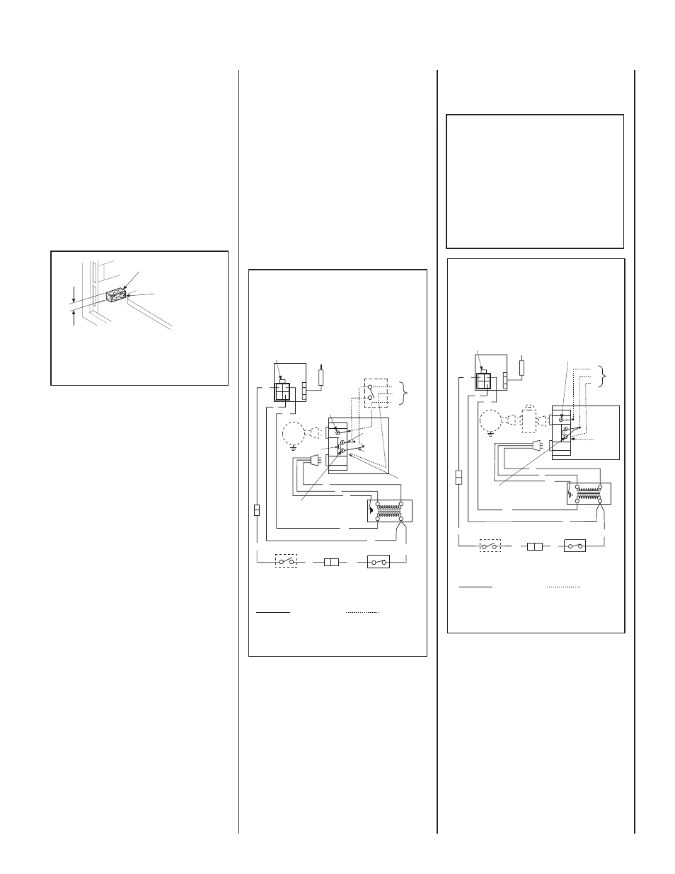
Figure 17
Figure 18
Figure 16
See Figure 4 on Page 5 for
Optional Electrical Inlet
Knockout Location.
* Field-Provided
Junction Box and
Duplex Receptacle
* Narrow (2 1/8 Inch Wide)
J-Box Required
Optional J-Box/Outlet Box
(Left Side Shown)
1. If any of the original wire as supplied must be replaced,
1.
it must be replaced with
Type AWM 105
°C – 18 GA. wire.
2. 120V, 60Hz – Less than 3 amps.
BK
Junction Box
Transf.
120 V.
24 V
Factory Wired
Field Wired
BL
Electronic Wiring Diagram (Honeywell)
Showing the Blower Wiring for the Optional
FBK-100 and FBK-200 Kits
R
W
BL
OPT
BLOWER
G
W
*OPTIONAL
ACCESSORY
SWITCH
120
VAC.
BK
W
Gas Valve
B
R
IGNITER
PILOT
ASSEMBLY
Break Off
Tab
BK
G
*Blower speed control switch is provided in FBK200 blower kit.
Outlet Box
Green Ground
Screw
Hot side of Outlet
Schematic Representation Only
**ON/OFF Switch (Integral
with Gas Valve)
**Leave the ON/OFF switch, which is integral
with the gas valve, in the ON position.
Red
pigtail
Black
pigtail
White Wire
to Opposite
Side
G
LIMIT SWITCH
OPTIONAL WALL SWITCH
OR OPTIONAL THERMOSTAT OR
OPTIONAL REMOTE RECEIVER
BK
BK
1. If any of the original wire as supplied must be replaced,
1.
it must be replaced with
Type AWM 105
°C – 18 GA. wire.
2. 120V, 60Hz – Less than 3 amps.
BK
Junction Box
Transf.
120 V.
24 V
Factory Wired
Field Wired
BL
Electronic Wiring Diagram (Honeywell)
Showing the Blower Wiring for the Optional
FBK-250 Kits
R
BL
OPT
BLOWER
G
W
120
VAC.
BK
W
Gas Valve
B
R
IGNITER
PILOT
ASSEMBLY
BK
Outlet Box Green
Ground Screw
Hot side of Outlet
Schematic Representation Only
*ON/OFF Switch (Integral
with Gas Valve)
White Wire
To Opposite
Side
Optional FBK-250
Module
*Leave the ON/OFF switch, which is integral
with the gas valve, in the ON position.
OPTIONAL ON/OFF SWITCH,
WALL SWITCH, THERMOSTAT
OR REMOTE CONTROL RECEIVER
G
W
LIMIT SWITCH
BK
BK