Warning – Maxon Telecom MPB3328CNE User Manual
Page 3
3
Electronic Models -
Electronic models have a fi xed rate gas valve.
Input of electronic models is shown in Table 2:
Millivolt Models with
Manually-Modulated Gas Valve
Natural Gas
Propane Gas
Model
Input Rate
(BTU/HR)
Input Rate
(BTU/HR)
MPB3328
13,500 to 17,500
13,500 to 17,500
MPB3530
16,000 to 20,000
16,500 to 20,000
MPB4035
24,000 to 30,000
22,300 to 28,000
MPB4540
24,750 to 31,000
23,000 to 29,000
Table 1
Electronic Models with
Fixed-Rate Gas Valve
Natural Gas
Propane Gas
Model
Input Rate
(BTU/HR)
Input Rate
(BTU/HR)
MPB3328
17,500
17,500
MPB3530
20,000
20,000
MPB4035
30,000
28,000
MPB4540
31,000
29,000
Table 2
These appliances are designed to operate on
natural or propane gas only.
Millivolt Models -
Millivolt models come standard with the manu-
ally-modulated gas valve; fl ame appearance
and heat output can be controlled at the gas
valve.
Input of millivolt models is shown in Table 1:
All Models -
Maximum manifold pressure is 3.5 in. w.c. (0.87
kPa) for natural gas and 10 in. w.c. (2.49 kPa)
for LP/Propane gas.
Installations at Altitudes of 0 to 4500 ft.-
Units are tested and approved for elevations
of 0 to 4500 feet (0 to 1372 meters).
Installations at Altitudes above 4500 ft.-
For elevations above 4500 feet (1372 meters),
install the unit according to the regulations of
the local authorities having jurisdiction and,
in the USA, the latest edition of the National
Fuel Gas Code (ANSI Z223.1) or, in Canada,
the latest edition of the CAN1-B149.1 and
.2 codes.
Table 3 shows the units' gas orifi ce size for
the elevations indicated.
Burner Orifi ce Sizes
Elevation 0-4500 feet ( 0-1372 meters)
Models
Natural
Gas
drill size (inches)
Propane
Gas
drill size (inches)
MPB-3328
#47 (.0785")
#1.2m (.048")
MPB-3530
#44 (.086")
#55 (.052")
MPB-4035
#37 (.104")
1/16" (.0625")
MPB-4540
#36 (.1065")
#52 (.0635")
Table 3
Do not use these appliances if any part has
been under water. Immediately call a qualifi ed,
professional service technician to inspect the
appliance and to replace any parts of the control
system and any gas control which have been
under water.
Ne pas se servir de cet appareil s'il a été plongé
dans l'eau, complètement ou en partie. Appeler
un technicien qualifi é pour inspecter l'appareil
et remplacer toute partie du système de con-
trôle et toute commande qui ont été plongés
dans l'lau.
This appliance may be installed in an after-
market permanently located, manufactured
home (USA only) or mobile home, where not
prohibited by local codes. This appliance is
only for use with the type of gas indicated
on the rating plate. This appliance is not
convertible for use with other gases, unless
a certifi ed kit is used.
Cet appareil peut être installé dans un maison
préfabriquée (É.-U. seulement) ou mobile
déjà installée à demeure si les réglements
locaux le permettent.
Cet appareil doit être utilisé uniquement
avec les types de gaz indiqués sur la plaque
signalétique. Ne pas l'utiliser avec d'autres
gaz sauf si un kit de conversion certifi é est
installé.
Millivolt appliances are fi tted with a SIT millivolt
gas control valve and have been tested with
and approved for use with this valve and are
listed accordingly.
Test gauge connections are provided on the front
of the millivolt gas control valves (identifi ed OUT
for the manifold side and IN for inlet pressure
side). A 1/8" NPT test gauge connection is
provided on the electronic gas control valve
adjacent to the outlet to the main burner.
Minimum inlet gas pressure to the appliance is
5.0 inches water column (1.24 kPa) for natural
gas and 11 inches water column (2.74 kPa) for
propane for the purpose of input adjustment.
Maximum inlet gas supply pressure to the ap-
pliance is 10.5 inches water column (2.61kPa)
for natural gas and 13.0 inches water column
(3.23 kPa) for propane.
The appliance must be isolated from the gas
supply piping system (by closing its individual
manual shut-off valve) during any pressure
testing of the gas supply piping system at
test pressures equal to or less than psig
(3.5) kPa).
The appliance and its individual shut-off valve
must be disconnected from the gas supply piping
system during any pressure testing of that system
at pressures in excess of psig (3.5 kPa).
These appliances must not be connected to a
chimney or fl ue serving a separate solid fuel
burning appliance.
Do not place clothing or other materials on or
near this appliance.
WARNING
These fi replaces are vented deco-
rative gas appliances. Do not burn
wood or other material in these
appliances.
WARNING
Failure to comply with the installa-
tion and operating instructions pro-
vided in this document will result in
an improperly installed and operat-
ing appliance, voiding its warranty.
Any change to this appliance and/or
its operating controls is dangerous.
Improper installation or use of this
appliance can cause serious injury
or death form fi re, burns, explosion
or carbon monoxide poisoning.
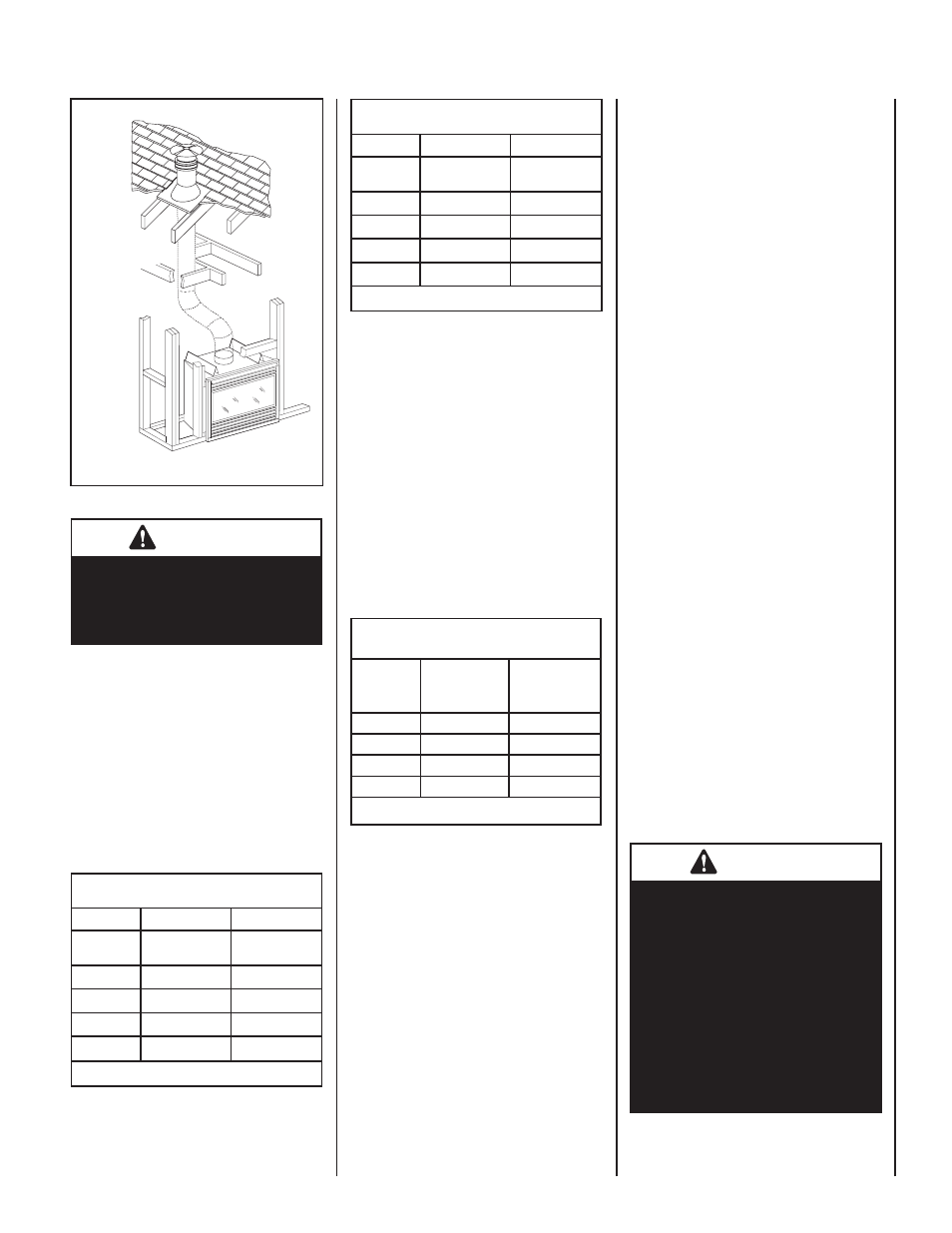
Figure 1b
Offset
Venting
Outside Air
Kit can be
installed as
shown in
Figure 1a.