Setup and adjustment, Assembly making adjustments – MTD 250 User Manual
Page 5
5
3
Setup and
Adjustment
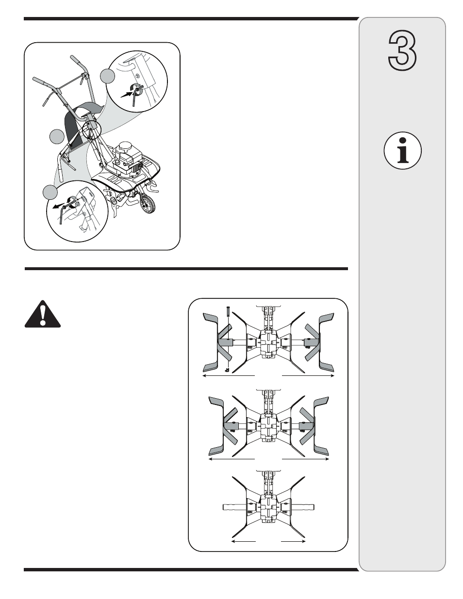
1. Remove the handle adjustment lever, Step 1
Figure 1.
2. Lift up the upper handle to raise into operation
position, Step 2 Figure 1.
3. Reinsert adjustment lever through the front
or rear hole (depending on desired setting),
and tighten the lever into the lock nut on the
retainer bracket.
4. Once the lever has been inserted, the handle
can be moved to the desired position and
tightened.
Figure 2 - Tine width adjustment
NOTE: Stand behind
the tiller as if you were
going to operate it.
Your right hand cor-
responds to the right
side of the tiller; your
left hand corresponds
to the left side of the
tiller.
Figure 1 - Assembling the Upper Handle
IMPORTANT
This unit is shipped
without gasoline or
oil in the engine. Fill
up gasoline and oil
as instructed in the
accompanying engine
manual
BEFORE oper-
ating your machine.
NOTE: This operator’s
manual may cover vari-
ous models of tillers.
The units illustrated
may vary slightly from
your unit. Follow only
those instructions
which pertain to your
model number.
Assembly
Making Adjustments
Warning: Disconnect the spark
plug wire and ground it against
the engine before performing
any adjustments.
Engine Adjustment
Refer to the separate engine manual for engine
adjustment instructions.
Depth Stake Adjustment
Refer to the Operating section for instructions
on adjusting the depth stake.
Tine Width Adjustment
The tilling width of the unit is 22 inches. Tilling
width can increase to 24 inches by removing
the clevis and cotter pins, sliding each outer
tine out one inch, and securing in this position
with the pins. For cultivation, reduce the tine
width to 13 inches by removing the outer tines
completely, Figure 2.
1
2
3
24-inch
13-inch
22-inch