Communication connections, Save – Motion 42-02-S028 User Manual
Page 12
MCE Universal Serial Network
6 Manual # 42-02-S028 A1
Communication Connections
Connections are described for IMC, PTC/PHC, and Motion 3000ES.
IMC
1. Connect the external Ethernet cable to Ethernet Port A
on the USN-BASE assembly.
2. Connect the supplied C-RJ11/DB9M cable from a con-
troller MC-RS (serial board) COM port to RS232 Port B
(J7) on the USN-BASE assembly.
3. Through the controller MPU board, set the connected
COM port to media= serial and device= PC.
4. On the MC-RS board, set the connected COM port slide
switch to DCE.
5. Press RSTA to reset the USN board so that it will read its
new connections.
If connecting an IMC group control:
1. Connect to the group controller using a CRT, terminal
emulator, or TigerTerm software.
2. Press F1, then 1 to get to the General configuration
screen.
3. Access the ICOM setting. Set it to the COM port con-
nected to the MC-USN board. For example, if the MC-
USN board is connected to COM2 on the MC-RS board,
set the ICOM setting to COM2.
4. Save.
5. With the Function Switch F8 switch UP (all others down), press N to cycle through the
menu to verify that information is correct.
• MC-USN version
• iReport version
• Number of cars connected
• Number of cars
• Number of floors
The controller is now ready to communicate.
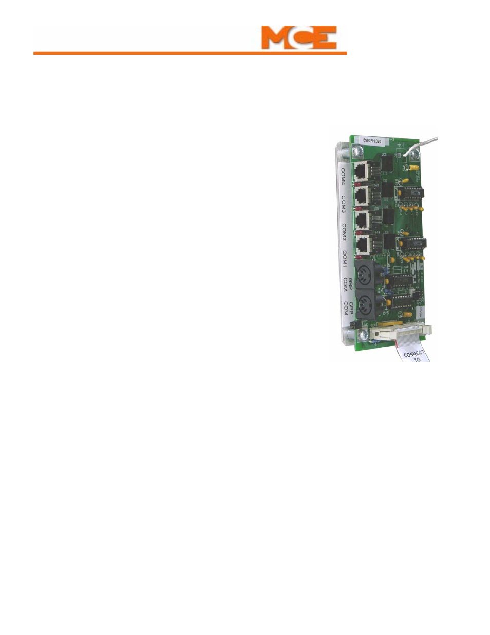
IMC: MC-RS Board