Meade Instruments 60AZ-A2 User Manual
Page 5
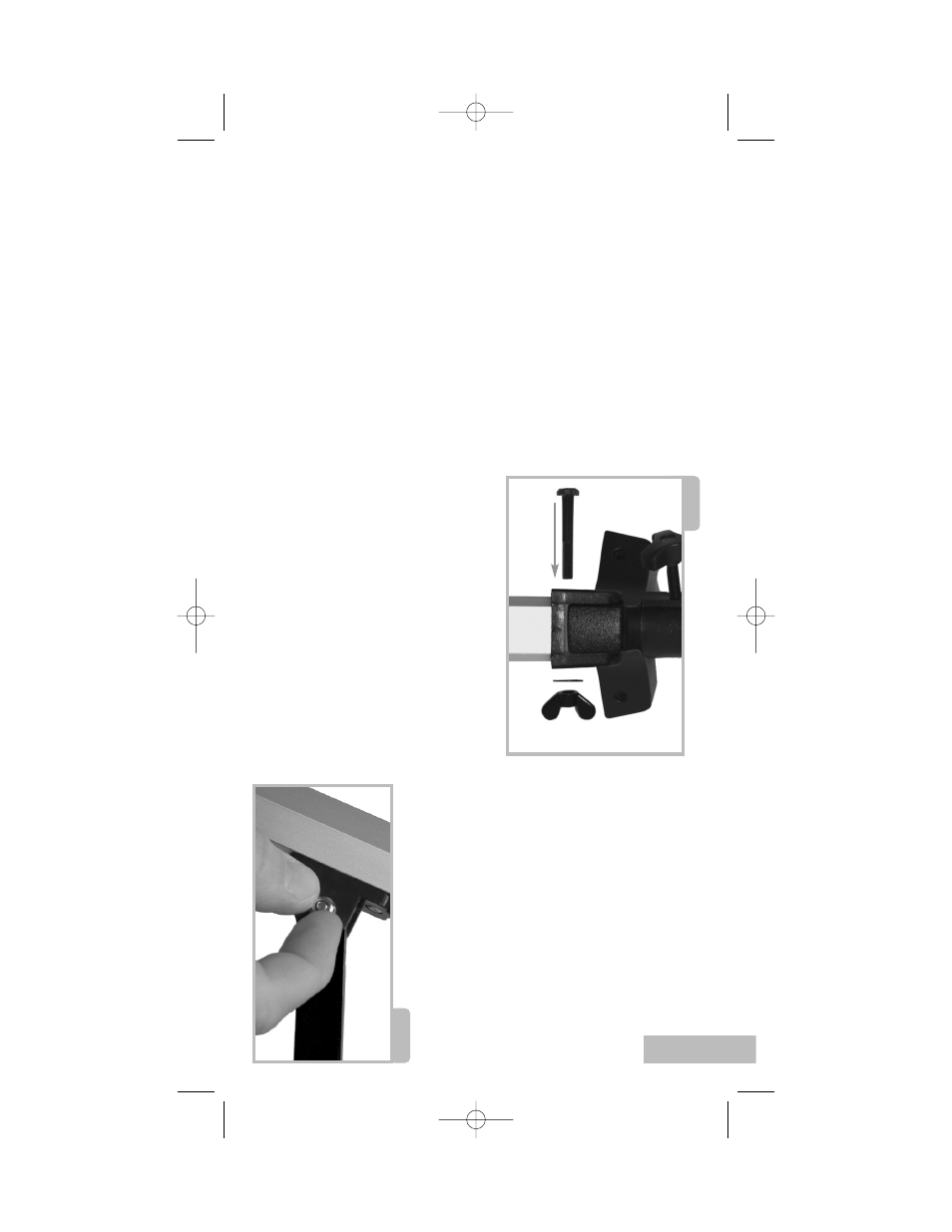
Fig. 3
Fig. 2
AS
SEMBLE Y
OUR TRIPOD
The tripod is the basic support f
or y
our
te
lesc
ope. Its height may be adjus
ted so that
you c
an view c
omf
ort
abl
y.
NN
oo
ttee
:: NN
uu
mm
bb
ee
rr
iinn
bb
rraa
cc
kk
ee
ttss
,, ee
..gg
..,,
((33
)),,
rree
ffee
rr
ttoo
FF
iigg
.. 11
..
1.
Mak
e sur
e that as y
ou att
ach the l
egs (7)
to
the mount that the l
eg br
ac
es (9) ar
e
facing inwar
d.
2.
Line up the hol
es at the t
op of one of the
legs with the hol
es in the mount (10). See
Fig. 2
.
3.
Thr
ead one of the 2-inch bolts thr
ough
the hol
es.
4.
Thr
ead a wingnut o
ver the bolt and hand-
tight
en t
o
a firm f
eel.
5.
Att
ach the r
emaining two l
egs t
o
the
mount in the same manner
.
6.
Spr
ead the l
egs out e
venl
y apart.
7.
Set the height of y
our tripod:
a.
Rot
at
e and l
oosen the l
eg l
ock
thumbscr
e
w
(20) t
o
unl
ock the l
eg l
ock.
b.
Slide the inner portion of the l
e
g (19) in
or out t
o
the desir
ed l
ength.
c.
Rot
at
e and tight
en the l
eg l
ock
thumbscr
e
w
t
o
r
e
lock the l
eg l
ock.
d.
Repeat f
or the other two l
egs.
A
T
T
A
CH THE A
CCES
SORY TRA
Y
The tr
ay helps s
tabilize the tripod and is also
a c
onv
enient holder of e
yepiec
es and other
Meade ac
c
e
s
sories, such as the Barl
o
w
l
ens.
1.
Line up the hol
es at the end of one of the
leg br
ac
e supports (8) with the hol
es in
one of the l
eg br
ac
es (9).
2.
Thr
ead one of the one-half inch bolts
thr
ough the hol
es.
3.
Thr
ead a he
x nut o
ver the end of the bolt.
4.
Finger tight
en the bolt and he
x nut. See
Fig. 3
.
5.
Repeat with the two other l
e
g
br
ac
es.
6.
Thr
ead the ac
c
e
s
sory tr
ay (26) o
ver
the c
ent
er mounting bolt t
o
a firm
feel.
A
T
T
A
CH THE OPTIC
AL TUBE T
O
THE MOUNT
The optic
al tube gather
s dis
tant light which
is f
ocused in the e
yepiec
e
.
1.
Remo
ve
the two l
o
ck knobs (5) fr
om the
optic
al tube.
2.
Slide the altitude r
od (17) int
o the hol
e in
the altitude adjus
tment c
ontr
ol . Tight
en
to
a firm f
eel. See
Fig. 4
.
3.
Plac
e the optic
al tube (4) between the
forks of the mount, orient
ed as shown in
Fig. 4
.
3
2” Scr
e
w
tripod
le
g
mount
washer
wingnut
finger tight
en the
he
x nut
40-04135 8 Page Manual Template 6/29/05 10:54 AM Page 5