Warning – Milwaukee RAVL42 User Manual
Page 34
34
NOTE: DIAGRAMS & ILLUSTRATIONS ARE NOT TO SCALE.
Vent Pipe Maintenance
Conduct an inspection of the venting system semi-annually. Recom-
mended areas to inspect are as follows:
1. Check areas of the venting system which are exposed to the elements
for corrosion. These will appear as rust spots, streaks, or in extreme
cases, holes. These components should be replaced immediately.
2. Remove the cap and shine a flashlight down the vent. Remove any
bird nests or other foreign material.
3. Check for evidence of excessive condensate, such as water droplets
forming in the inner liner and subsequently dripping out at joints.
Continuous condensate can cause corrosion of caps, pipe and fittings.
It may be caused by having excessive lateral runs, too many elbows,
or exterior portions of the system being exposed to cold weather.
4. Inspect joints to verify that no pipe sections or fittings have been dis-
turbed and consequently loosened. Also check mechanical supports
such as wall straps or plumbers’ tape for rigidity.
CAUTION: Wear gloves and safety glasses for protection while
doing required maintenance.
Verify proper operation after servicing.
S'assurer que l'appareil fonctionne adéquatement une fois
l'entretien terminé.
Maintenance Checklist
The following should only be performed by a qualified service techni-
cian.
1. Annual inspection should be made and the following checks per-
formed:
o
When unit is cool, glass viewing door and inspect burner for dirt, soot
and lint accumulations and remove if necessary. If excessive soot ac-
cumulation is present on burner, have a qualified service technician
adjust the burner for proper combustion.
o
Clean inside of glass with gas fireplace glass cleaner. NEVER attempt
to remove or clean the glass when the unit is hot.
o
Check the hot air outlet vents for lint or other accumulations. Never
block or restrict vent openings, obstruct flow of ventilation air, or use
vents other than those approved for use with this appliance.
o
Check that direct-vent pipe, air intake and flue are open and free of
soot, blockage, or debris.
o
Check gaskets once a year. Gaskets must be tight. Replace if neces-
sary.
o
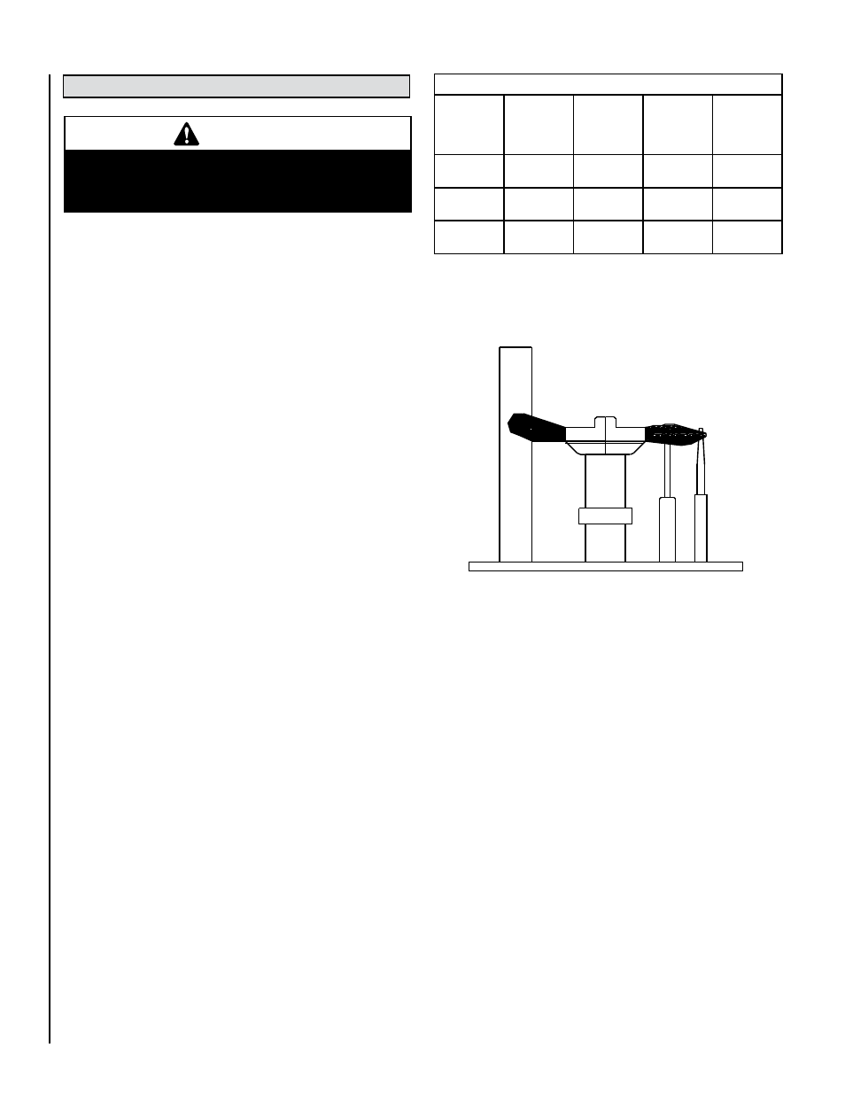
Inspect the pilot system for proper flame. NEVER ADJUST THE PILOT
until after the gas pressure has been checked and supply lines have
been completely bled (this may take an hour or more when bleeding
through the pilot). All pilots are checked and burned at the factory prior
to shipment. The pilot adjustment screw is located to the upper right
of the flame height control knob. Adjust the pilot screw to properly
size the flames. Flames should completely surround the thermopile
and thermocouple and extend across the main burner tube ports. Be
careful not to back the screw out of its threads. Check for gas leaks
using a gas leak test solution.
o
Check that the area around the fireplace is kept clear and is free of
combustible materials, gasoline and other flammable vapors and
liquids.
o
Check the millivolt system as per the table on this page.
2. The viewing glass should be cleaned periodically (see Glass Main-
tenance).
3. Should repairs or maintenance of the fireplace require the disas-
sembly of the vent/air intake system, the reassembly and resealing
should be completed by a qualified service technician and follow
the instructions on Page 17 of this manual.
Millivolt and System Checks
Check
Test
To
Test
Connect
Meter
Leads to
Terminals
Thermostat
Connects
Meter Read-
ing
Should Be
A
Complete
System
2 & 3
Closed
100 MV
or More
B
Thermopile
Output
1 & 2
Open
Greater Than
325 MV
C
System
Resistance
2 & 3
Closed
2.5 Ohms
Proper Pilot Flame Appearance
Figure 48
MAINTENANCE AND SERVICING
WARNING
Turn off gas and electrical power to the fireplace
and allow it to cool before cleaning or servicing
the appliance.