Thermocouple input terminals (c0h/c0l to c7h/c7l), Ground terminals (gnd), Power terminals (+5v) – Measurement Specialties USB-5201 User Manual
Page 15: Digital terminals (dio0 to dio7)
USB-5201 User's Guide
Sensor Connections
15
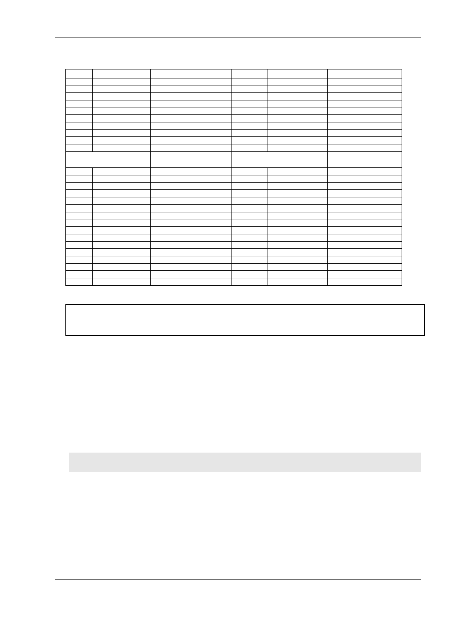
USB-5201 screw terminal descriptions
Pin
Signal Name
Pin Description
Pin
Signal Name
Pin Description
1
RSVD
Reserved, Do Not Use
27
RSVD
Reserved, Do Not Use
2
NC
Not connected
28
GND
Ground
3
C0H
CH0 sensor input (+)
29
C7L
CH7 sensor input (-)
4
C0L
CH0 sensor input (-)
30
C7H
CH7 sensor input (+)
5
NC
Not connected
31
RSVD
Reserved, Do Not Use
6
RSVD
Reserved, Do Not Use
32
NC
Not connected
7
C1H
CH1 sensor input (+)
33
C6L
CH6 sensor input (-)
8
C1L
CH1 sensor input (-)
34
C6H
CH6 sensor input (+)
9
GND
Ground
35
NC
Not connected
10
RSVD
Reserved, Do Not Use
36
RSVD
Reserved, Do Not Use
CJC sensor
CJC sensor
11
RSVD
Reserved, Do Not Use
37
RSVD
Reserved, Do Not Use
12
NC
Not connected
38
GND
Ground
13
C2H
CH2 sensor input (+)
39
C5L
CH5 sensor input (-)
14
C2L
CH2 sensor input (-)
40
C5H
CH5 sensor input (+)
15
NC
Not connected
41
RSVD
Reserved, Do Not Use
16
RSVD
Reserved, Do Not Use
42
NC
Not connected
17
C3H
CH3 sensor input (+)
43
C4L
CH4 sensor input (-)
18
C3L
CH3 sensor input (-)
44
C4H
CH4 sensor input (+)
19
GND
Ground
45
NC
Not connected
20
RSVD
Reserved, Do Not Use
46
RSVD
Reserved, Do Not Use
21
+5V
+5V output
47
+5V
+5V output
22
GND
Ground
48
GND
Ground
23
DIO0
Digital Input/output
49
DIO7
Digital Input/output
24
DIO1
Digital Input/output
50
DIO6
Digital Input/output
25
DIO2
Digital Input/output
51
DIO5
Digital Input/output
26
DIO3
Digital Input/output
52
DIO4
Digital Input/output
Use 16 AWG to 30 AWG wire for your signal connections.
Tighten screw terminal connections
When making connections to the screw terminals, fully tighten the screw. Simply touching the top of the screw
terminal is not sufficient to make a proper connection.
Thermocouple input terminals (C0H/C0L to C7H/C7L)
You can connect up to eight thermocouples to the differential sensor inputs (C0H/C0L to C7H/C7L). The USB-
5201 supports type types J, K, R, S, T, N, E, and B thermocouples.
Ground terminals (GND)
The six analog ground terminals (
GND
) provide a common ground for the input channels and DIO bits and are
isolated (500 VDC) from the USB GND.
Power terminals (+5V)
The two
+5V
output
terminals are isolated (500 VDC) from the USB +5V.
Caution! Each +5V terminal is an output. Do not connect to an external power supply to these terminals or
you may damage the USB-5201 and possibly the computer.
Digital terminals (DIO0 to DIO7)
You can connect up to eight digital I/O lines to the screw terminals labeled
DIO0
to
DIO7
. Each terminal is
software-configurable for input or output.
If a digital bit is set up as an alarm, the bit is configured for output on power-up, and assumes the state defined
by the alarm configuration.