Connecting a dvd player or other s-video device, Dvd player with component video (recommended), Other s-video device – MITSUBISHI ELECTRIC WD-62327 User Manual
Page 16: Figure 9), Figure 10)
16
17
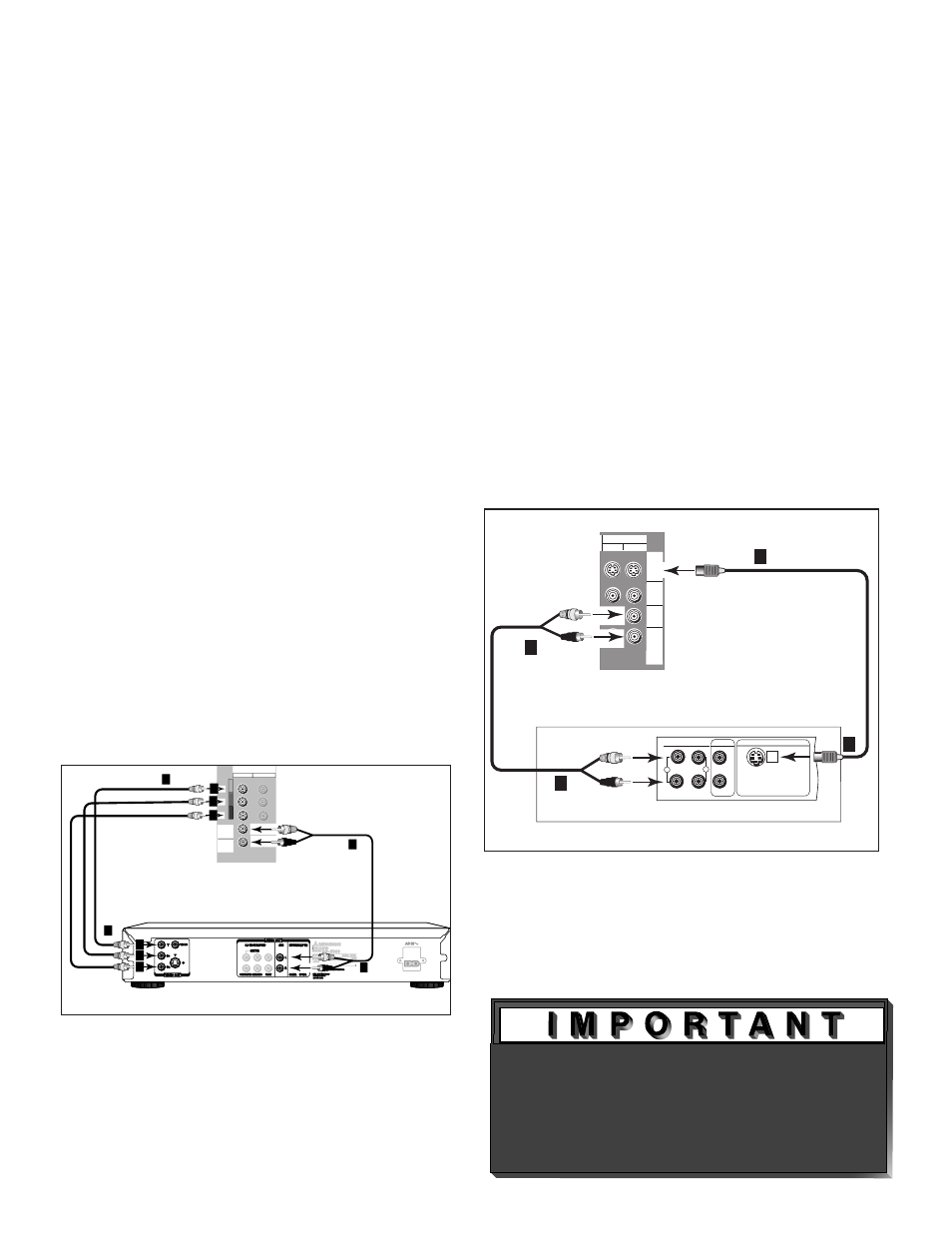
DVD Player with Component Video
(Recommended)
(Figure 9)
1. Connect the Component Video cables from
(YCb Cr or Y Pb Pr) VIDEO OUT on the back of the
DVD player to COMPONENT (1 or 2) on the TV
back panel. The correct connections are:
A. Y to Y
B. Cb or Pb to Pb
C. Cr or Pr to Pr
2. Connect a set of audio cables from AUDIO OUT on
the back of the DVD player to COMPONENT AUDIO
Input (1 or 2) on the TV back panel.
• The red cable connects to the R (right)channel
• The white cable connects to the L (left) channel
Note: Some video game systems support DTV
resolutions via component connections.
Please refer to your video game console
Owner’s Guide for setup information.
Note: For optimal DVD playback performance,
Mitsubishi recommends using a progressive
scan DVD player, set to play in progressive
scan mode. You will also want to set your
player to display 16:9 widescreen. Please
refer to your DVD player’s Owner’s Guide.
�����
�
�
�
�
�
�
���������
���������
��������
������������������
��������������
����������������
�����
���
� � � � �
�
�
������
� ��� �
������
���� �
������
� � � ��
�������
�
�
�
�
�����
���
Figure 9. Connecting a DVD Player with Component
Video.
Figure 10. Connecting an S-Video Device.
�����
�
�
��
��
����� ���
�������������
��� �� ��������
���
�
�
������
��������� ��������
�����
������� �������
����� ���
�� ��
����������
��� ������
�����
�������
����� ������
����� ����
����� �����������
���
���������� ������� �����������
����������� ��
���� �������� ����
������� �� �����
���� �� �����
�������� ����
������ ���
������������
���������
��� � � ����� �����
�
�
�
� �
��
����� �
�����
� � �� �
� �����
����� �
�
���
�����
���
��� ���� �����
�
�
�
�
�����
�
�
�
�
�
Connecting a DVD Player or Other S-Video Device
See Appendix B, page 59, for
component video signal compatibility
information.
For digital audio connections, see your
Other S-Video Device
(Figure 10)
1. Connect an S-Video cable from VIDEO OUT on the
device back panel to VIDEO INPUT-1 or INPUT-2
on the TV back panel.
2. Connect a set of audio cables from AUDIO OUT on
the device back panel to AUDIO INPUT-1 or INPUT-
2 on the TV back panel, matching the input used in
step 1.
• The red cable connects to the R (right) channel
• The white cable connects to the L (left) channel
If your S-Video Device is mono (non-stereo), connect
only the white (left) cable.