Operating instructions, Camera set-up, Fig. 4 – Miller Compass 20 User Manual
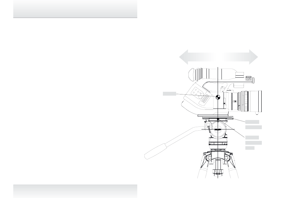
Page 7: Fig. 5
2. Camera Set-up
2.1 Remove the CAMERA PLATE by pulling down the SAFETY
TAB while rotating the QUICK RELEASE KNOB to the left.
The CAMERA PLATE should pop out.
2.2 Refer to the Camera’s owners manual for correct method of
attachment to the CAMERA PLATE. Inspect the CAMERA
PLATE and remove the 1/4” and 3/8” screws (for HDV
mount) or the 1/4” + PIN CARRIAGE (XDCAM/P2HD mount)
as required. The 1/4”and 3/8” screws can be stored
underneath the SLIDING PLATFORM (fig. 1).
2.3 Attach camera accessories and the battery to the camera,
it is recommended to estimate the camera’s Centre of
Gravity (C of G) for the purpose of correctly positioning
the camera on the CAMERA PLATE. The camera’s C of G
can be estimated by placing the camera on to a round rod
and then shifting it backwards or forwards until a balance
point – C of G - is achieved. It is recommended to identify
this point on the camera as it will be useful in step 2.5.
2.4 Attach the CAMERA PLATE to the camera or the QUICK
RELEASE TRIPOD ADAPTOR and securely tighten the
screws.
2.5 Align the CAMERA PLATE with the SLIDING PLATFORM
and slide it in until the safety mechanism is engaged.
2.6 Release the SLIDING PLATFORM LOCK and slide the
SLIDING PLATFORM such that the camera’s C of G is
directly above the centre axis of the Fluid Head and tighten
the SLIDING PLATFORM LOCK (fig.5). If this can not be
achieved then reposition the CAMERA PLATE on the
Camera or the QUICK RELEASE TRIPOD ADAPTOR – step
`
2.4. This will ensure that the system has maximum stability.
6
C of G
Fig. 4
Operating Instructions
Fig. 5
Sliding
platform
lock
Sliding
platform