Mts-4a c, Rray, Esign – Meyer Sound MTS-4A User Manual
Page 11: Requencies, Oading, Overage, Aximum
A
RRAY
D
ESIGN
FOR
L
OW
F
REQUENCIES
Since the MTS-4A contains sub and low frequency drivers, in
addition to mid and high drivers, array design for the MTS-4A
must incorporate the different array response of high and low
frequencies. The beam width for a single speaker widens as
the frequency decreases. Frequencies below 125 Hz are mostly
omnidirectional while higher frequencies are more directional.
NOTE: H and V are abbreviations for horizontal and vertical.
The low frequencies of adjacent arrayed speakers exhibit
on-axis addition and off-axis cancellation, resulting in a
narrowing of coverage in the dimension in which they are
arrayed. A H array of two MTS-4As narrows the H coverage
without affecting the V coverage. A V array of two MTS-4As
narrows the V, without affecting the H coverage. In both
cases, there is 3 to 6 dB SPL of on-axis low frequency (LF)
addition compared to a single MTS-4A. Due to the larger
distance between LF drivers in V, compared to H arrays, the
V coverage narrows at a faster rate than does the H coverage
for H arrays, given the same array size and adjacent speaker
placement.
Increasing the number of MTS-4As in the array increases the
LF directional control. A properly designed V array steers
low frequencies to include balconies and upper tiers, while
a H array focuses low frequencies for longer throw distances
without interacting with the walls.
L
OADING
One of the most important factors governing LF response is
speaker placement with respect to adjacent surfaces. The MTS-
4A gains significant LF power by coupling with nearby floors
and walls. Half-space loading describes a speaker coupling
with one surface. Speakers placed on the floor benefit
from half-space loading, while flown speakers in free-space
(without a nearby wall or ceiling) do not. In general,
subwoofers in half-space generate twice the SPL (+6 dB)
compared to the same number in free-space.
NOTE: SPL values refer to an on-axis measurement position.
The actual SPL addition and narrowing of coverage
varies with frequency and depends on the physical
displacement between cabinets, loading conditions, and
room acoustics.
MTS-4A C
OVERAGE
AND
M
AXIMUM
SPL
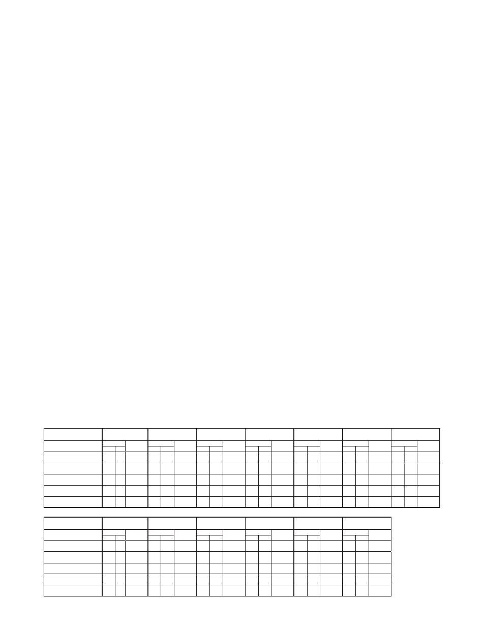
A series of outdoor tests was conducted at Meyer Sound to
determine the coverage angle and on-axis SPL for arrays with
one and two horizontal rows of up to five speakers each, at
numerous splay angles. The measurements were conducted at
a distance of 8 m with half-space loading; on-axis SPL values
were interpolated from 8 to 1 m. The coverage angle for the
array is the result of averaging the –6 dB points from 125
Hz to 8 kHz.
The horizontal angles in the tables below represent the
optimal narrow (15°), middle (30°), and wide (45°)
orientations for the MTS-4A. The vertical splay angles
represent the optimal narrow and wide configurations. 2@0°
LT denotes long throw: the two horns are coupled directly
together (top speaker upside down/bottom speaker upright) to
form a single narrow horn.
The table on this page shows the SPL and coverage angles
that result from grouping the MTS-4A in arrays of up to five
units horizontally and two rows vertically. All splay angles
refer to the angle between cabinet centers.
If this information does not address your application
requirements, contact Meyer Sound to obtain additional
information on array design.
MTS-4A Array Coverage and Maximum SPL
Number of Horizontal
MTS-4As @ Angle
1
2 @ 15˚
2 @ 30˚
2 @ 45˚
3 @ 15˚
3 @ 30˚
3 @ 45˚
Coverage
M ax Peak
Coverage
M ax Peak
Coverage
M ax Peak
Coverage
M ax Peak
Coverage
M ax Peak
Coverage
M ax Peak
Coverage
M ax Peak
H
V
dB SPL
H
V
dB SPL
H
V
dB SPL
H
V
dB SPL
H
V
dB SPL
H
V
dB SPL
H
V
dB SPL
Vertical Rows of MTS-4As
@ Angle
1
70˚ 60˚
140
50˚
60˚
146
60˚
60˚
145
100˚
60˚
142
80˚
60˚
149
120˚
60˚
147
150˚
60˚
145
2 @ 0˚ (LT)
70˚ 30˚
146
50˚
30˚
152
60˚
30˚
151
100˚
30˚
148
80˚
30˚
155
120˚
30˚
153
150˚
30˚
151
2 @ 15˚
70˚ 50˚
145
50˚
50˚
151
60˚
50˚
150
100˚
50˚
147
80˚
50˚
154
120˚
50˚
152
150˚
50˚
150
2 @ 30˚
70˚ 90˚
143
50˚
90˚
149
60˚
90˚
148
100˚
90˚
145
80˚
90˚
152
120˚
90˚
150
150˚
90˚
148
Number of Horizontal
MTS-4As @ Angle
4 @ 15˚
4 @ 30˚
4 @ 45˚
5 @ 15˚
5 @ 30˚
5 @ 45˚
Coverage
M ax Peak
Coverage
M ax Peak
Coverage
M ax Peak
Coverage
M ax Peak
Coverage
M ax Peak
Coverage
M ax Peak
H
V
dB SPL
H
V
dB SPL
H
V
dB SPL
H
V
dB SPL
H
V
dB SPL
H
V
dB SPL
Vertical Rows of MTS-4As
@ Angle
1
100˚ 60˚
151
140˚
60˚
148
190
60˚
146
110˚
60˚
153
180˚
60˚
148
240
60˚
146
2 @ 0˚ (LT)
100˚ 30˚
157
140˚
30˚
154
190
30˚
152
110˚
30˚
159
180˚
30˚
154
240
30˚
152
2 @ 15˚
100˚ 50˚
156
140˚
50˚
153
190
50˚
151
110˚
50˚
158
180˚
50˚
153
240
50˚
151
2 @ 30˚
100˚ 90˚
154
140˚
90˚
151
190
90˚
149
110˚
90˚
156
180˚
90˚
151
240
90˚
149
11