Array design – Meyer Sound MTS-4A User Manual
Page 10
We do not recommend using phase poppers to analyze driver
polarity. The phase response for all drivers varies, to some
degree, over the frequency range in which it operates. Since
the phase popper, a popular but inaccurate tool, does not
discern variations in phase response with respect to frequency,
it provides no useful information about the phase response
through the crossover, the most important consideration for
determining correct driver polarity.
Phase poppers are, therefore, not useful for performing phase
measurements on an individual loudspeaker or a full-range
sound system containing one or more crossovers. If necessary,
apply a phase popper only to loudspeakers with identical
drivers without a crossover, and check the system’s overall
phase response with a frequency analyzer and/or listening
test.
NOTE: Since polarity reversal causes excessive driver excursion
at high source levels, use moderate levels for these
tests.
D
RIVER
P
OLARITY
IN
THE
S
AME
L
OUDSPEAKER
Use the following test procedure to verify polarity between
drivers in the same loudspeaker:
1. Place a measurement microphone 3 ft from the front of
the loudspeaker at the midway point between the 12” and
15” drivers.
2. Connect a signal source to the loudspeaker and note the
frequency response.
The polarity is correct if the frequency response is smooth
through each crossover region (40 Hz, 100 Hz, 1 kHz).
Cancellation greater than 6 dB in any region indicates polarity
reversal between the drivers on either side of that crossover
point.
P
OLARITY
B
ETWEEN
A
DJACENT
L
OUDSPEAKERS
Use the following test procedure to verify the polarity
between two adjacent loudspeakers of the same type:
1. Position two loudspeakers adjacent to each other.
2. Place a measurement microphone 3 ft from the speakers on
the axis between them.
3. Connect a signal source to one speaker and note the
frequency response and overall level.
4. Apply the same signal to the second speaker with the first
speaker still connected.
The polarity is correct if the frequency response remains
constant with a significant increase in amplitude. Broadband
cancellation (decreased overall level) indicates polarity
reversal.
NOTE: Polarity tests among more than two speakers may
damage the drivers in the cabinet with reversed
polarity.
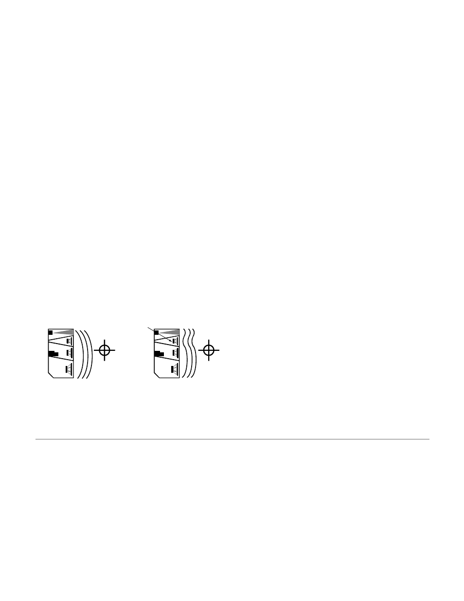
Drivers with correct
polarity cause acoustic
addition
Drivers with reversed
polarity cause acoustic
cancellation
This driver is 180 out of
phase to the other drivers
ARRAY DESIGN
B
ACKGROUND
Creating an effective array with the MTS-4A requires a precise
understanding of how to combine the coverage area and SPL
of the individual speaker with those of adjacent speakers.
Array design is a trade-off between increasing on-axis power
and creating smooth transitions between the coverage areas
of adjacent speakers.
As the splay angle (the angle between adjacent cabinet faces)
decreases below the coverage angle of the individual speaker,
the on-axis power increases, but the coverage overlap between
adjacent speakers causes comb filtering and other frequency
response variations.
As the splay angle increases toward the coverage angle,
the on-axis power decreases, but the variations in frequency
response diminish. As the splay angle increases beyond the
coverage angle, noticeable gaps begin to form in the array’s
coverage area.
NOTE: The trapezoidal shape of the MTS-4A does not represent
the horizontal coverage area of the speaker. Tight-
packing MTS-4As results in the minimum recommended
splay angle (15°) for horizontal arrays.
10