Manley DIGITAL TO ANALOGUE CONVERTER HDCD DAC 1993 - 2000 User Manual
Page 8
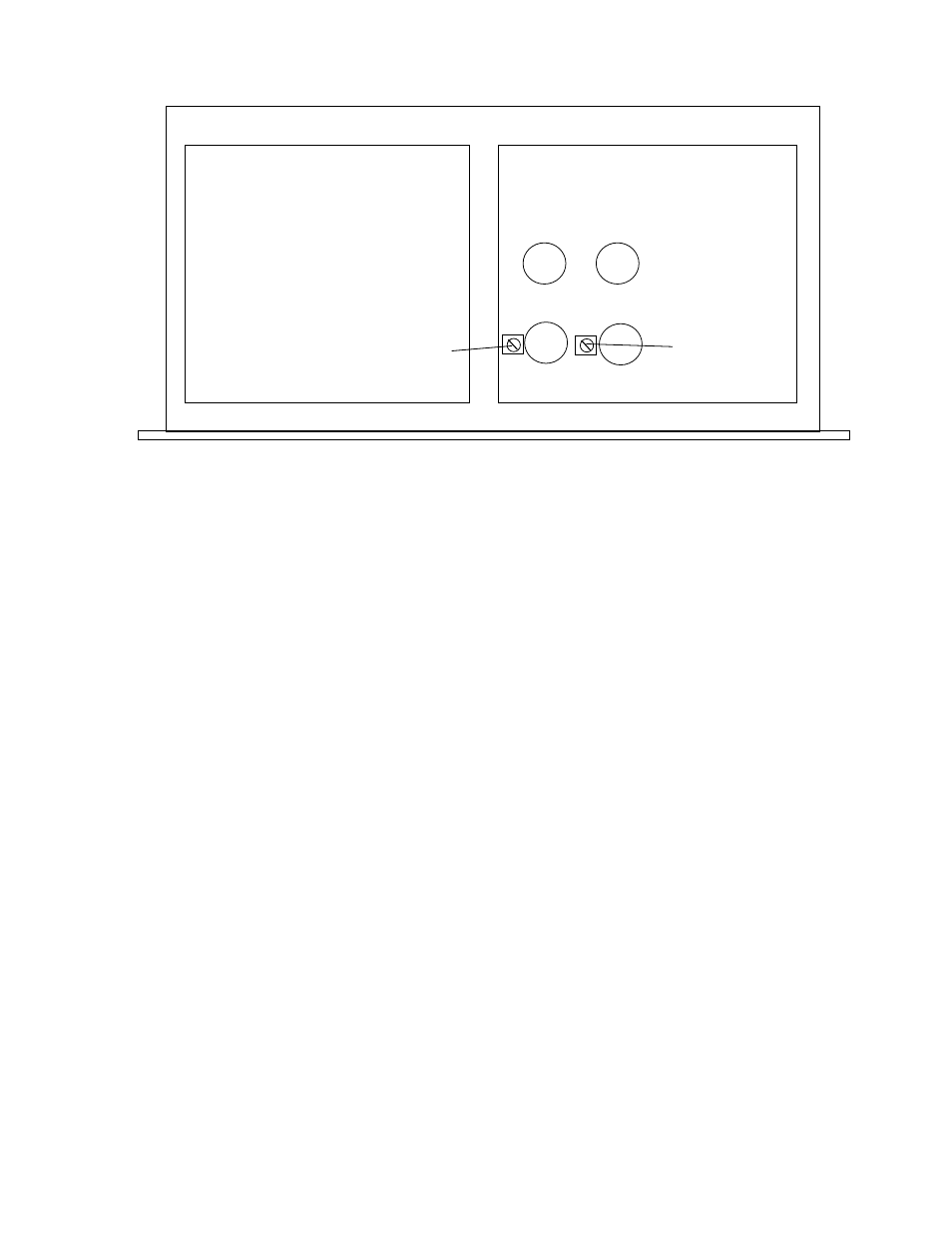
5751
5751
7044
7044
LEFT RIGHT
GOLD
PLATED
DIGITAL
BOARD
DGND
AGND
LEFT
GAIN
TRIM
RIGHT
GAIN
TRIM
Theoutput level of the DAC is set at the factory. If it is not optimum it is possible for you to adjust it to match
your system. We use a standard test CD with a 1 KHz "full scale" (maximum digital value) and adjust the trimmers for
2.0 volts AC RMS measured at the output jacks. This is a standard of sorts followed by many manufacturers. If adjusted
for 4 volts at the output, the signal will be 6 dB louder, which is like getting 3 more clicks on the volume control. A 1
volt output will be 6 dB quieter. You can also do this roughly "by ear" - Listen to music on the left side only and adjust
until you are satisfied with the level - then turn on the right side and adjust the right trimmer until the stereo balance is
right by your ears or mono music (not tones) is in the middle, between the speakers. You should use tones if you are
adjusting by meter, and music if adjusting by ear. It is not difficult but be careful - high voltages are right around the
tubes. Use an insulated screwdriver, keep one hand in your pocket and don't touch the screwdriver to any other parts.
We expect most users to get 5 to ten years of life from the factory supplied tubes. Sometimes this is optimistic.
If replacing one or all tubes do not attempt to use any but the same type tube as removed. The pin-out of the 7044 is
unusual and most tubes will not work. The 5751 is a tube preferred by Manley because of its fidelity, low noise and
exceptionally low microphonics. The latter is critical due to the fact that the gain control is ahead of the tube line
amplifiers and does not attenuate any tube "problems". Manley always has good tubes in stock if needed.
The all tube line amplifier is a combination of our tried and true totem output but with a new differential input.
We use the Ultra-Analog converters in a differential mode. We use what is considered 2 stereo converters. Here, the left
and right halves of each converter are working in opposing polarities, thus cancellation of distortion and noise is
maximized. This requires that subsequent analog filtering at 300 kHz, the stepped attenuators and the input to the line
amp be doubled. The first stage of the line amp acts to cancel noise and distortion through high common mode rejection.
The RCA output recieves its output directly from the plate output through an expensive MIT MULTICAP. The
XLR gets its signal through a custom 1:1 Manley transformer. In the professional world where balanced lines are
standard, transformers are acknowledged as the absolute best (and most expensive) technique. Not only does a
transformer provide a true balanced output, it can also be "floating" which isolates grounds from one piece of equipment
from the next if needed. A transformer also tends to isolate the line driver from the cable. Capacitance and back EMF
seem to cause less problems related to the feedback loop.
On the diagram above you might notice the AGND and DGND designations. These refer to "Analog Ground"
(tubes, etc.) and "Digital Ground" (chips). Normally these are joined with a short wire. In some situations we have found
cutting the wire between the grounds helps to remove noise. It seems to depend on external factors and might solve a
noise problem if you have one or suspect you have one. Let us know which way worked for you. Send us a fax at (909)
628-2482 or EMAIL us at emanley@ netcom.com so that we can compile a database. Thanks.