MACKIE SP1200 User Manual
Page 5
SP1200 – 5
The PAGING MIC VOX variable control adjusts
the ducking threshold for the paging mic. Rotate the
control clockwise to reduce the threshold. Rotate the
control counterclockwise to increase the threshold.
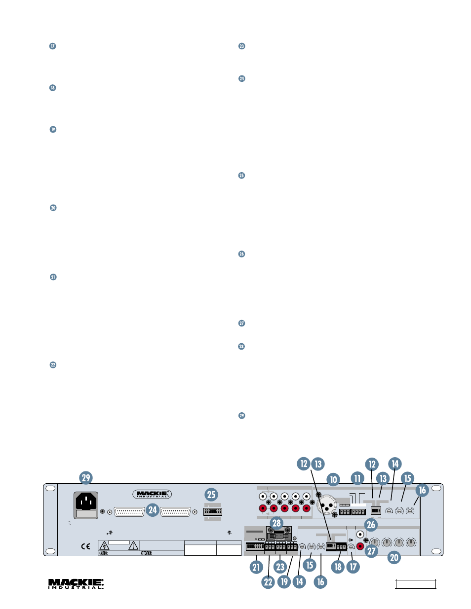
MIC/LINE INPUT is provided to connect a local
microphone. This is a 3-pin Phoenix-type connector
where pin 1 is ground, pin 2 is signal high (+), and
pin 3 is signal low (–).
AMBIENT MIC is a 3-pin Phoenix-type connector
used to connect the optional MT-3100 ambient
microphone. This microphone is used to detect the
ambient noise level in the room. The
microprocessor uses this information to adjust the
paging mic level above the ambient noise. The
ambient mic also provides an input for the optional
DSP card when it is installed.
EQ is a 3-band equalizer with a sweepable
midrange that only affects Inputs 1-4. LOW is a
shelving filter that provides 15 dB of boost and cut
below 80Hz. MID is a peaking filter that provides
15 dB of boost and cut at the selected frequency
between 250Hz and 8kHz. HIGH is a shelving filter
that provides 15 dB of boost and cut above 12kHz.
AMP ADDRESS is used to assign a unique
address to the amplifier, as well as to enable or
disable features. Switches 1-5 provide 32 separate
addresses, switch 6 determines Master/Slave
status, switch 7 enables Input 4 Priority, and switch
8 enables the optional ambient mic. Any two
amplifiers assigned to the same address can be
controlled by a single remote control when
connected together via the RS485 ports.
RS485 is a 3-pin Phoenix-type connector in the
zone that provides an interface for the SPLinker
Sound Palette Control PC application software for
centralized computer control of up to 32 zones, as well
as communication between SP1200s and SP2400s.
When two SP1200s are linked via their RS485
connectors and assigned the same AMP ADDRESS
(switches 1-5), the front panel controls and remote
controls operate both amplifiers.
REMOTE is a 3-pin Phoenix-type connector for
the optional wired remote control (SP-41R), which
provides Input Select and Master Volume control.
EXPANSION IN/OUT consists of two parallel 25-
pin D-Sub connectors for connecting multiple
SP1200s and SP2400s together in a serial fashion.
Any of the four program sources from any SP1200
and SP2400 can be used as the source for any of
the zones in the system by assigning it to the
expansion bus with the internal Bus Assign switches.
This is a balanced bus for the four stereo input
sources. In addition, the paging mic and paging control
signal are also provided on the EXPANSION bus.
LOCAL/REMOTE is a set of eight DIP switches
used to select the input source for each input. Each
program input has two switches, one to select the
left signal source (odd-numbered switches) and one
to select the right signal source (even-numbered
switches). Move the switches up to select the local
program source, and down to select the remote
(external) program source from the EXPANSION bus.
PRE OUT is an unbalanced RCA jack that
provides a line-level signal from the preamplifier
stage of the SP1200. This provides a method for
inserting an external signal processor into the signal
chain prior to the amplifier stage. The U-shaped
jumper wire should remain installed between the
PRE OUT and AMP IN jacks for normal operation.
AMP IN is an unbalanced RCA jack that accepts
a line-level signal. See PRE OUT above.
ZONE A OUTPUT is a 2-pin Phoenix-type
connector that provides speaker-level signals.
The
SP1200 is shipped with the outputs configured for
70-volt operation in U.S. versions, and 100-volt
operation in European versions. Internal jumpers are
provided to configure the amplifier for 8 ohm
systems as well. See page 14 for more information.
Connect the supplied AC linecord to the IEC AC
Socket. The AC line fuse is contained in the socket,
behind the cover located at the bottom of the
socket. Use replacement fuses only as indicated on
the rear panel.
PHANTOM
PAGING
GAIN +40dB
MIC/LINE INPUT A
CAUTION:
TO REDUCE THE
RISK OF FIRE REPLACE WITH SAME
TYPE FUSE AND RATING
115V 60Hz FUSE 115/ T4A 120 WATTS
230V 50Hz FUSE 230/ T2A 120 WATTS
1 2 3 4
1 2 3 4 5 6 7 8
0
I
PROGRAM EQ
1 2 3 4
ZONE
A
GAIN +40dB
PHANTOM
ON
THE FOLLOWING ARE TRADEMARKS OR REGISTERED TRADEMARKS OF MACKIE DESIGNS INC
"MACKIE.","MACKIE INDUSTRIAL", AND THE "RUNNING MAN" FIGURE. COPYRIGHT ©2000 ALL RIGHTS RESERVED
CONCEIVED, DESIGNED, AND MANUFACTURED BY MACKIE DESIGNS INC. • WOODINVILLE • WA • MADE IN USA • FABRIQUE AU USA
PARALLEL
INPUTS
G +
–
CONTROL
GROUND
ALL CALL
DIRECT
R
OUTPUT
PROGRAM INPUTS
1
2
3
4
PRIORITY
L
HIGH
U
+12
–12
U
+12
–12
LOW
GAIN
+
-
HIGH 12k
FREQ
MID
LOW 80Hz
U
+15
–15
U
+15
–15
U
+15
–15
1K
3K
400
8k
250
HIGH
U
+12
–12
U
+12
–12
LOW
GAIN
+
-
+
-
AMP IN
PRE OUT
PAGING MIC
EXPANSION IN
EXPANSION OUT
AMP ADDRESS
RS485
REMOTE
AMBIENT
MIC
MIC
VOX
RISK OF ELECTRIC SHOCK
DO NOT OPEN
REPLACE WITH THE SAME TYPE FUSE AND RATING.
DISCONNECT SUPPLY CORD BEFORE CHANGING FUSE
UTILISE UN FUSIBLE DE RECHANGE DE MÊME TYPE.
DEBRANCHER AVANT DE REMPLACER LE FUSIBLE
WARNING:
TO REDUCE THE RISK OF FIRE OR ELECTRIC SHOCK, DO NOT
EXPOSE THIS EQUIPMENT TO RAIN OR MOISTURE. DO NOT REMOVE COVER.
NO USER SERVICEABLE PARTS INSIDE. REFER SERVICING TO QUALIFIED PERSONNEL.
CAUTION
AVIS:
RISQUE DE CHOC ELECTRIQUE — NE PAS OUVRIR
SERIAL NUMBER
MANUFACTURING DATE
ZONE A
OUTPUT SUITABLE
FOR CLASS 2 WIRING
100/ 70V/8
+
–
1
2
3
G
+
–
A
G
B
1 2 3 4 5 6 7 8
LOCAL
1
2
3
4
REMOTE
1
2
3
4
SP1200
MUSIC CONTROLLER