Internal settings, Connecting the rs485 serial port, Bus assign – MACKIE SP1200 User Manual
Page 13
SP1200 – 13
Connecting the RS485 Serial Port
This is a 3-pin Phoenix-type connector that
follows standard RS485 protocol. Select either a
data-grade shielded twisted pair cable or a standard
3-conductor microphone cable for this connection.
The RS485 port is wired as follows:
Pin 1 = A (non-inverting I/O)
Pin 2 = G (Ground)
Pin 3 = B (inverting I/O)
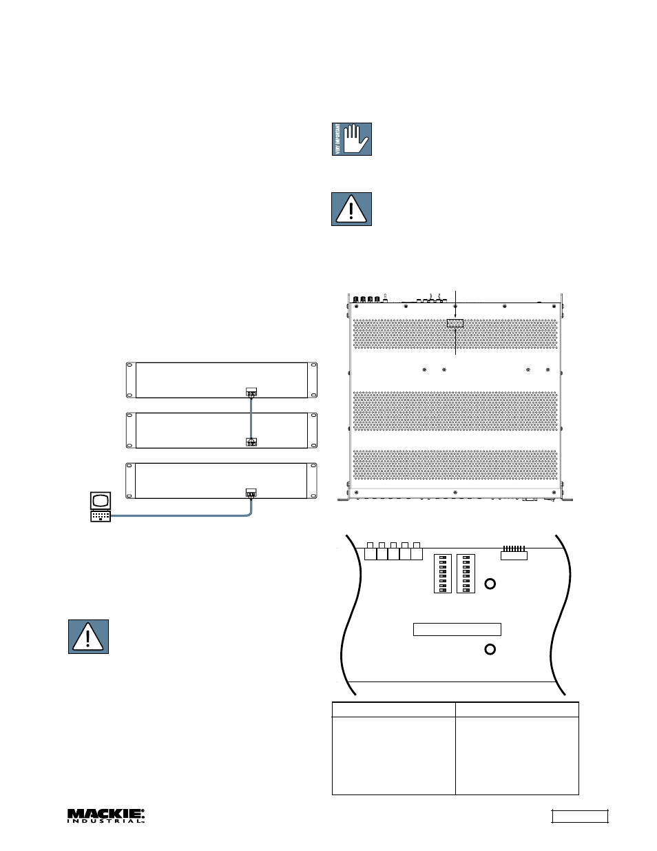
The SPLinker Sound Palette Control PC
application uses the RS485 serial port to connect
between a computer and the SP1200. Connect the
PC RS485 port to the first SP1200, and then inter-
connect up to two SP1200s in the system using
their RS485 connections.
Note: It may be necessary to install an RS485
interface card in the PC, or to use an RS232 to
RS485 converter.
Two SP1200s can be connected together for
stereo operation (each SP1200 assigned the same
AMP ADDRESS, with one assigned Master, and the
other Slave).
RS485
RS485
RS485
Laptop with
SPLinker PC Application
or
Internal Settings
Note: There are several settings that can be
changed inside the SP1200. These settings should
be made prior to installing the SP1200.
CAUTION: These servicing instructions
are for use by qualified personnel only. To
avoid electric shock, do not perform any
servicing other than that contained in the Operating
Instructions unless you are qualified to do so.
Refer all servicing to qualified service personnel.
Make sure the power is off and the power cord
disconnected before removing the top cover to gain
access to the inside of the SP1200.
Bus Assign
There are two 8-position DIP switches on the
Input Board that allow you to assign a Program
Input source to the balanced expansion bus. Each
Program Input Source has four corresponding
switches: Left (+), Left (–), Right (+), and Right (–).
Typically, you would move all four switches either
down (off) or up (on to assign to expansion bus).
Note: These DIP switches can be
accessed without removing the cover of
the unit. A flathead screwdriver at least 2"
(50.8 mm) long, and no larger in diameter than 1/8"
(3.175 mm) is required. See illustration below.
CAUTION: When using multiple SP1200s
that use the expansion bus, these switch
settings
must be unique to each unit or
you can damage your SP1200(s). Never assign
more than one program source to the same channel
on the Expansion Bus.
Insert screwdriver through grill hole to adjust DIP switches.
Use a flashlight to aid in viewing the DIP switches.
Approximate location of Bus Assign DIP switches.
Bus Assign DIP Switch Location
S3
J8
J9
J10
J11
J12
S1
S2
SP1200 INPUT BOARD
REAR PANEL
12345678
ON
12345678
ON
Signal
Switch No.
Input 1 Left (+)
S1-1
Input 1 Left (–)
S1-2
Input 1 Right (+)
S1-3
Input 1 Right (–)
S1-4
Input 2 Left (+)
S1-5
Input 2 Left (–)
S1-6
Input 2 Right (+)
S1-7
Input 2 Right (–)
S1-8
Signal
Switch No.
Input 3 Left (+)
S2-1
Input 3 Left (–)
S2-2
Input 3 Right (+)
S2-3
Input 3 Right (–)
S2-4
Input 4 Left (+)
S2-5
Input 4 Left (–)
S2-6
Input 4 Right (+)
S2-7
Input 4 Right (–)
S2-8
Bus Assign Switch Chart