McIntosh MC1.2KW User Manual
Page 13
13
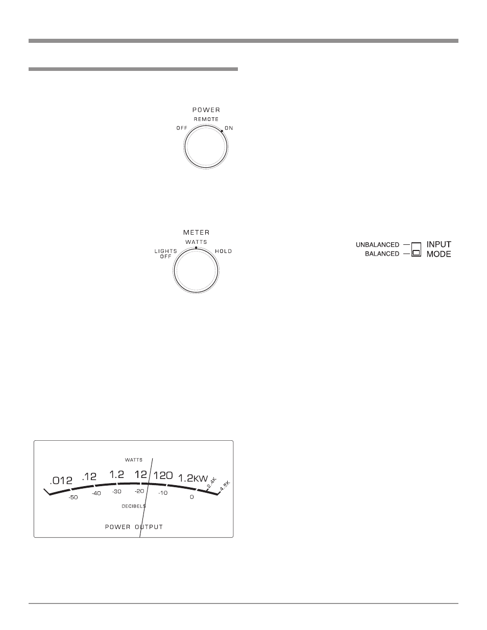
electronically held to this power level until
a higher power peak passes through the
amplifier. The meter pointer will then rise
to the newer higher indication. If no further
power peaks are reached, the meter pointer
will very slowly return to its rest position or
lower power level. The decay rate is approxi-
mately 6dB per minute.
Note: The MC1.2KW Power Output Meter
indicates the actual wattage delivered
to the loudspeakers by responding to
the combination of current and voltage
output.
Input Mode Switch
The Input Mode Switch, which is located on the Rear Panel
of the MC1.2KW, allows
you to select either the
Balanced or Unbalanced
Input. Refer to figure 11.
Power On
To have the MC1.2KW automatically turn On or Off when
a control center turns on or off, rotate the power switch to
the remote position. For manual opera-
tion, rotate the power switch to the
On or Off position as desired. Refer to
figure 8.
Note: There must be a power control
connection between the MC1.2KW
and the McIntosh Control Center,
in order for the remote power
turn-on to function.
Meter Selection
Rotate the meter mode switch to select the meter operation
mode you desire. Refer to figures
9 and 10.
Lights Off - Meter lights are
turned off and the
meter will contin-
ue to indicate the
power output.
Note: When Power
Control
Input of the MC1.2KW is connected to a
McIntosh A/V Control Center or Pream-
plifier with Remote Meter Illumination
Control, the Meter Illumination will
automatically be remotely controlled
(On/Off) with the METER Switch to set
to the WATTS or HOLD position.
Watts- The meters respond to all the musical in-
formation being produced by the amplifier.
They indicate to an accuracy of at least 95%
of the power output with only a single cycle
of a 2000Hz tone burst.
Hold - The meter pointer is locked to the highest
power peak in a sequence of peaks. It is
How to Operate
How to Operate
Figure 8
Figure 9
Figure 10
Figure 11