Finding crankshaft horizontal centerline, X” dimension) – Mercury INSTALLATION MANUAL D7.3L D-TRONIC User Manual
Page 25
D7.3L D-TRONIC DIESEL ENGINES - BRAVO MODELS
Page 25 of 90
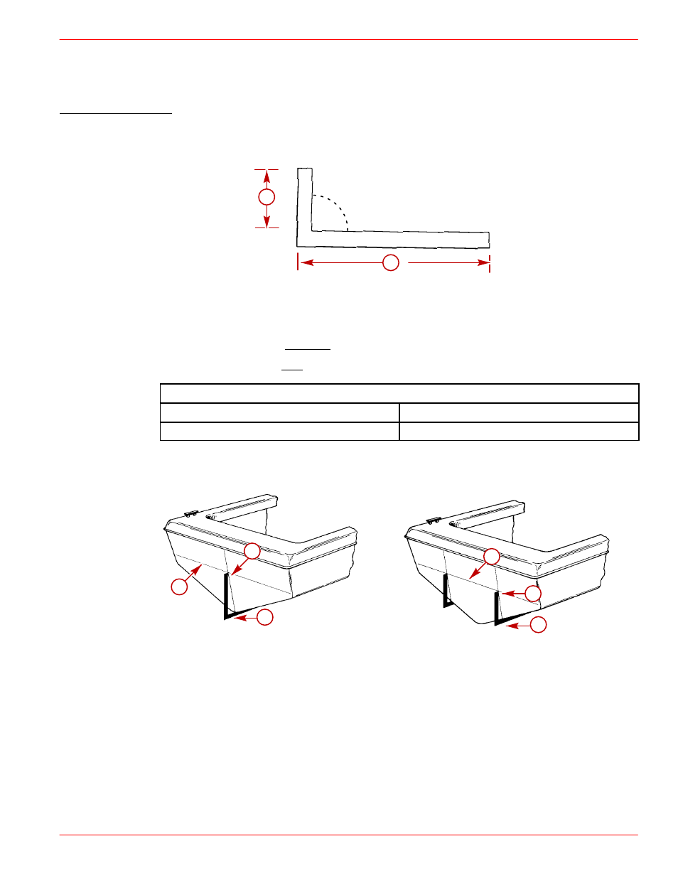
Finding Crankshaft Horizontal Centerline (“X” Dimension)
“X” Dimension can be measured by the “90
°
Tool Method” or by the “Tape Measure Method.”
90
°
TOOL METHOD
1. Construct 90
°
tool.
71621
90
°
b
a
a -
Dimension from Chart Below
b -
Measurement: 4 ft. (1.2 m)
To Lower Drive Unit -
Subtract from dimension “a”.
To Raise Drive Unit -
Add to dimension “a”.
90
°
TOOL VERTICAL DIMENSION CHART
Sterndrive Unit
Location
Bravo One/Two/Three
13-9/16 in. (345mm)
IMPORTANT: This dimension should only be raised or lowered after proper testing.
2. Determine “X” Dimension location of crankshaft centerline(s).
71622
71623
c
a
b
c
b
a
Single Engine
Dual Engine
a -
Place 90
°
Tool Along Boat Bottom at Vertical Centerline
b -
Point at Which Top of Tool Contacts Transom on Vertical Centerline is Crank-
shaft Horizontal Centerline.
c -
Draw a Line Perpendicular to Vertical Centerline at Crankshaft Horizontal
Centerline.