Memorex MM1920 User Manual
Page 9
LED indicator
Green/Blue
Red
Power
consumption
100W(maximum)
Less than 5W
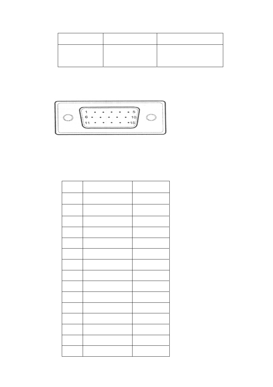
The following figure is the view looking into the pin end of video connector
The following table provides the pin numbers and corresponding pin assignments for
video connector with the DDC2B capability::
Number
RGB Mode Signal
Signal Pin
1 RED Pin#
1
2 Green Pin#
2
3 Blue Pin#
3
4 Ground Pin#
4
5 Ground Pin#
5
6 Red
Ground Pin#
6
7 Green
Ground Pin#
7
8 Blue
Ground Pin#
8
9 Empty Pin#
9
10 Sync
Ground Pin#
10
11 Empty Pin#
11
12
Bi-Directional Data(SDA)
Pin# 12
13 Horizontal
Sync Pin#
13
14
Vertical Sync
Pin# 14
15
Data Clock (SCL).
Pin# 15
9