Insert (ch. 1 to 8), Mon send 1 and mon send 2, Fx send 1 and fx send 2 – MACKIE PPM1012 User Manual
Page 12: Ppm1012, Ppm101
1
PPM101
PPM1012
The monitor outputs are not affected by the main
fader [59], or the channel faders [40]. This allows you
to set up the monitor mixes and levels just right, and
not have them change every time a channel level or the
main mix level is adjusted. This is the main aim of a
monitor mix: independence from the main mix.
11. FX SEND 1 and FX SEND 2
These 1/4" TRS connectors allow you to send the FX
line-level outputs to external effects processors, while
disconnecting the internal effects processors.
FX send 1 and FX send 2 are independent of each
other, so you can set up two separate effects processors.
The FX 1 output signal is the mix of all the channels
whose FX 1 control [35] is set to more than minimum.
The FX 2 signal is the mix of all the channels whose FX
2 control [36] is set to more than minimum.
The FX outputs here do not include processed audio
from the internal effects processors. When something
is plugged into one of these outputs, the signals that
normally feed the internal effects processor are discon-
nected, and come out of these outputs instead. This
prevents you from doubling-up on effects.
Both FX outputs are affected by the channel level
faders [40]. This allows you to set up the FX level just
right, and have it follow any change made to the chan-
nel levels.
In normal use, the unprocessed (dry) mono FX sends
would go to an external effects processor. The stereo
processed (wet) output from the external effects pro-
cessor would connect to the stereo FX returns [12]. The
FX return faders [57] allow you to adjust how much of
the wet signals appear in the main mix.
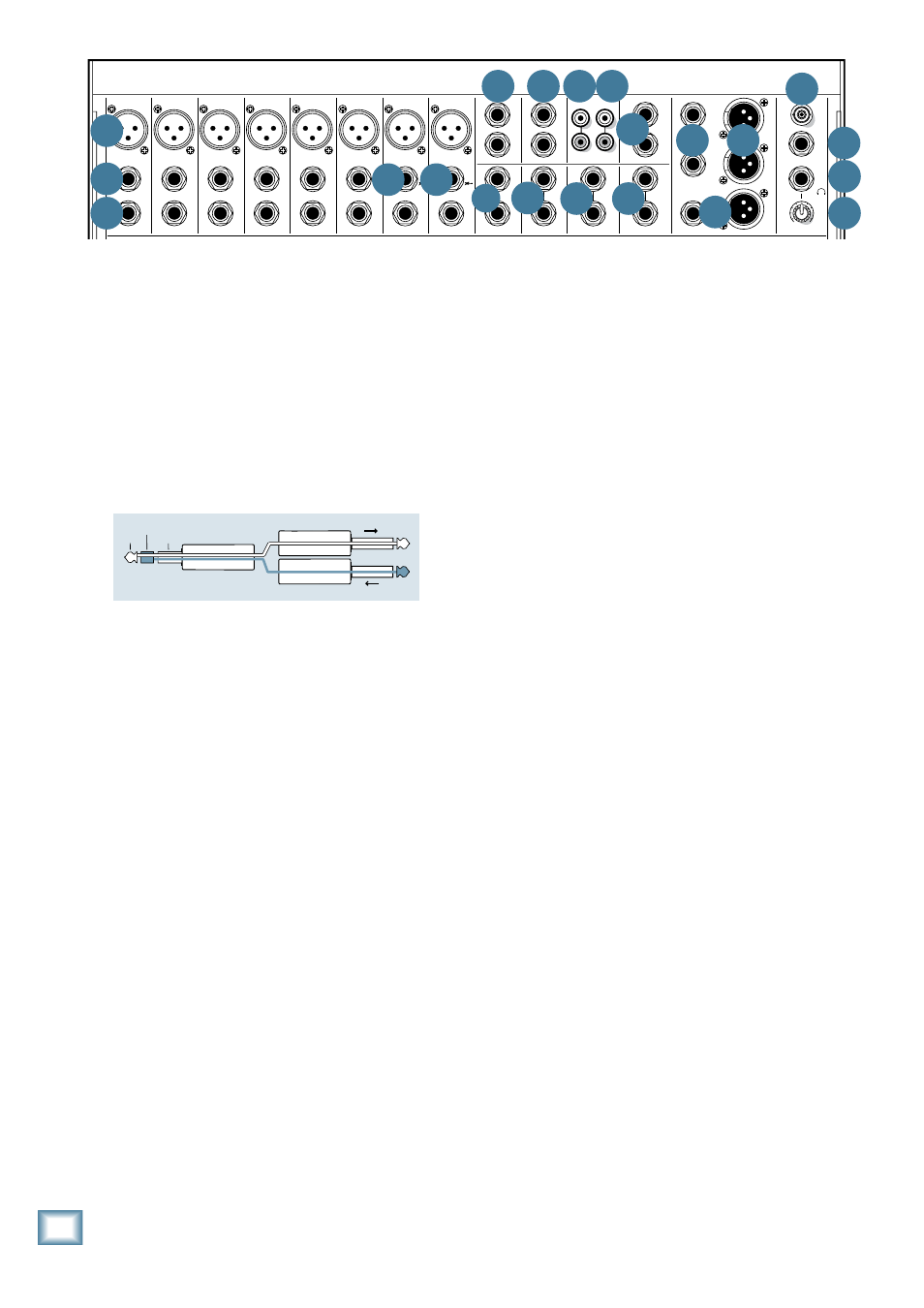
9. INSERT (Ch. 1 to 8)
These unbalanced 1/4" jacks on channels 1 to 6, are
for connecting serial effects processors such as com-
pressors, equalizers, de-essers, or filters. The insert
point is after the gain control [23] and compressor [25]
circuits (on channels 1 – 6), but before the channel’s
EQ [27-32] and fader [40]. The channel signal can go
out of the insert jack to an external device, be processed
(or whatever) and come back in on the same insert
jack. To do this requires a special insert cable that must
be wired thusly:
Tip = send (output to effects device)
Ring = return (input from effects device)
Sleeve = common ground
Insert jacks can be used as channel direct outputs;
post-gain, and pre-EQ. See the connector section on
page 30 (figure G) showing three ways to use insert
cables.
10. MON SEND 1 and MON SEND 2
These 1/4" TRS connectors allow you to send the
monitor line-level output to stage monitors. These could
either be passive stage monitors powered by an external
amplifier, or powered stage monitors with their own
amplifier built in.
Mon send 1 and mon send 2 are independent of each
other, so you can set up two separate monitor mixes. If
you only need to set up one monitor mix, use monitor 1,
as it has its own graphic EQ [45].
The monitor 1 signal is the sum (mix) of all the
channels whose mon 1 control [33] is set to more than
minimum. The monitor 2 signal is the sum (mix) of all
the channels whose mon 2 control [34] is set to more
than minimum. The overall monitor 1 output level can
be adjusted with the mon 1 master level fader [58] and
its EQ tweaked with the monitor 1 graphic EQ [45].
“tip”
This plug connects to one of the
mixer’s Channel Insert jacks.
“ring”
tip
ring
sleeve
SEND to processor
RETURN from processor
(TRS plug)
80Hz
LOW
MIC
1
MIC
2
MIC
3
MIC
4
MIC
5
MIC
6
MIC
7
MIC
8
INPUT
(BAL/UNBAL)
(BAL/UNBAL)
(BAL/UNBAL)
(BAL/UNBAL)
(BAL/UNBAL)
(BAL/UNBAL)
(BAL/UNBAL)
(BAL/UNBAL)
INSERT
INSERT
INSERT
INSERT
INSERT
INSERT
INSERT
INSERT
GAIN
U
-20
LAMP
12V 0.5A
L
R
FX SEND
TAPE
OUT
IN
L
MON SEND
FX RTN
(MONO)
MID
FREQ
R
L
U
GAIN
MI
C GAIN
0
+50
-20dB
+30dB
600
1.5k
150
8k
100
OFF
MAX
U
GAIN
MI
C GAIN
0
+50
-20dB
+30dB
U
GAIN
MI
C GAIN
0
+50
-20dB
+30dB
U
GAIN
MI
C GAIN
0
+50
-20dB
+30dB
U
GAIN
MI
C GAIN
0
+50
-20dB
+30dB
U
GAIN
MI
C GAIN
0
+50
-20dB
+30dB
U
GAIN
MI
C GAIN
0
+50
-20dB
+30dB
U
GAIN
MI
C GAIN
0
+50
-20dB
+30dB
1
9/10
11/12
2
3
4
5
6
7
8
SOLO
OL
+10
0
-20
SOLO
OL
+10
0
-20
1
9/10
11/12
2
3
4
5
6
7
8
EQ
EQ
OFF
MAX
OFF
MAX
OFF
MAX
OFF
MAX
OFF
MAX
12kHz
HI
LOW CUT
100 Hz
U
+15
-15
U
+15
-15
U
+15
-15
U
+15
-15
+20
12kHz
HI
80Hz
LOW
HI
MID
2.5kHz
LOW
MID
400Hz
U
+15
-15
U
+15
-15
U
+15
-15
U
+15
-15
12kHz
HI
80Hz
LOW
HI
MID
2.5kHz
LOW
MID
400Hz
GAIN
U
-20
PAN
AUX
SEND
EQ
COMP
COMP
COMP
COMP
COMP
COMP
+20
1
2
L
R
(MONO)
L
R
(MONO)
L
R
(MONO)
1
2
FX RTN
L
R
L
R
M
L
R
M
MON
1
MON
2
FX
1
FX
2
U
+15
O
O
U
+15
O
O
U
+15
O
O
U
+15
O
O
-15
U
+15
-15
U
+15
-15
U
+15
80Hz
LOW
MID
FREQ
R
L
600
1.5k
150
8k
100
EQ
12kHz
HI
PAN
AUX
SEND
MON
1
MON
2
FX
1
FX
2
U
+15
O
O
U
+15
O
O
U
+15
O
O
U
+15
O
O
-15
U
+15
-15
U
+15
-15
U
+15
80Hz
LOW
MID
FREQ
R
L
600
1.5k
150
8k
100
EQ
12kHz
HI
PAN
AUX
SEND
MON
1
MON
2
FX
1
FX
2
U
+15
O
O
U
+15
O
O
U
+15
O
O
U
+15
O
O
-15
U
+15
-15
U
+15
-15
U
+15
80Hz
LOW
MID
FREQ
R
L
600
1.5k
150
8k
100
EQ
12kHz
HI
PAN
AUX
SEND
MON
1
MON
2
FX
1
FX
2
U
+15
O
O
U
+15
O
O
U
+15
O
O
U
+15
O
O
-15
U
+15
-15
U
+15
-15
U
+15
80Hz
LOW
MID
FREQ
R
L
600
1.5k
150
8k
100
EQ
12kHz
HI
PAN
AUX
SEND
MON
1
MON
2
FX
1
FX
2
U
+15
O
O
U
+15
O
O
U
+15
O
O
U
+15
O
O
-15
U
+15
-15
U
+15
-15
U
+15
80Hz
LOW
MID
FREQ
R
L
600
1.5k
150
8k
100
EQ
12kHz
HI
PAN
AUX
SEND
MON
1
MON
2
FX
1
FX
2
U
+15
O
O
U
+15
O
O
U
+15
O
O
U
+15
O
O
-15
U
+15
-15
U
+15
-15
U
+15
80Hz
LOW
MID
FREQ
R
L
600
1.5k
150
8k
100
EQ
12kHz
HI
PAN
AUX
SEND
MON
1
MON
2
FX
1
FX
2
U
+15
O
O
U
+15
O
O
U
+15
O
O
U
+15
O
O
-15
U
+15
-15
U
+15
-15
U
+15
80Hz
LOW
MID
FREQ
R
L
600
1.5k
150
8k
100
EQ
12kHz
HI
PAN
AUX
SEND
MON
1
MON
2
FX
1
FX
2
U
+15
O
O
U
+15
O
O
U
+15
O
O
U
+15
O
O
R
L
PAN
AUX
SEND
MON
1
MON
2
FX
1
FX
2
U
+15
O
O
U
+15
O
O
U
+15
O
O
U
+15
O
O
R
L
PAN
AUX
SEND
MON
1
FX
MON
2
FX
1
FX
2
U
+15
O
O
U
+15
O
O
U
+15
O
O
U
+15
O
O
-15
U
+15
-15
U
+15
-15
U
+15
1
FX 2
9
1
2
10
/
INPUT
11 12
/
MAIN OUT
MAIN INSERT
TAP
DELAY
INT FX
MUTE
TAP
DELAY
INT FX
MUTE
TAP TO EDIT
01 PLATE REVERB
02 VOCAL PLATE
03 WARM ROOM
04 BRIGHT ROOM
13 CHORUS
14 CHORUS + REVERB
15 DOUBLER
16 TAPE SLAP
05 WARM LOUNGE
06 SMALL STAGE
07 WARM THEATER
08 BRIGHT STAGE
09 WARM HALL
10 CONCERT HALL
11 CATHEDRAL
12 GATED REVERB
17 DLY 1 BRIGHT (350ms)
18 DLY 1 WARM (300ms)
19 DLY 2 BRIGHT (250ms)
20 DLY 2 WARM (200ms)
21 DLY 3 BRIGHT (175ms)
22 DLY 3 WARM (150ms)
23 CHORUS + DLY (300ms)
24 REVERB + DLY (200ms)
15
15
10
10
5
5
0
15
15
10
10
5
5
0
16K
8K
4K
2K
1K
500
250
125
63
HI-Z
HI-Z
OL
4
6
3
10
15
7
10
20
30
0
2
U
+20
O
O
TAPE IN
BREAK
MUTES
CH 1-12
U
+15
O
O
U
+15
O
O
TO MON 1
TO MON 2
FX 1
FX 1
MONO OUT
LPF
O
O
MAX
75Hz
100
180
120
200Hz
0dB = 0dBu
LEVEL
SET
RUDE
SOLO
MAIN
MON 2
EQ ASSIGN
MAIN
METERS
R
L
PHANTOM
POWER
MAIN EQUALIZER
MON 1 EQUALIZER
15
15
10
10
5
5
0
15
15
10
10
5
5
0
16K
8K
4K
2K
1K
500
250
125
63
SIG/OL
SIG/OL
U
+15
O
O
SEND MASTER
U
+15
O
O
SEND MASTER
LOW CUT
100 Hz
LOW CUT
100 Hz
LOW CUT
100 Hz
LOW CUT
100 Hz
LOW CUT
100 Hz
LOW CUT
100 Hz
LOW CUT
100 Hz
dB
10
O
O
5
5
U
dB
30
20
10
O
O
40
50
5
5
U
60
SOLO
OL
+10
0
-20
dB
30
20
10
O
O
40
50
5
5
U
60
SOLO
OL
+10
0
-20
dB
30
20
10
O
O
40
50
5
5
U
60
SOLO
OL
+10
0
-20
dB
30
20
10
O
O
40
50
5
5
U
60
SOLO
OL
+10
0
-20
dB
30
20
10
O
O
40
50
5
5
U
60
SOLO
OL
+10
0
-20
dB
30
20
10
O
O
40
50
5
5
U
60
SOLO
OL
+10
0
-20
dB
30
20
10
O
O
40
50
5
5
U
60
SOLO
OL
+10
0
-20
dB
30
20
10
O
O
40
50
5
5
U
60
SOLO
OL
+10
0
-20
dB
30
20
10
O
O
40
50
5
5
U
60
SOLO
dB
30
20
10
O
O
40
50
5
5
U
60
SOLO
dB
30
20
10
O
O
40
50
5
5
U
60
SOLO
dB
30
20
10
O
O
40
50
5
5
U
60
SOLO
dB
30
20
10
O
O
40
50
5
5
U
60
dB
30
20
10
O
O
40
50
5
5
U
60
FX RTN
1
FX RTN
2
MON
1
MON
2
MAIN
FOOTSWITCH
TIP: FX1
RING: FX2
PHONES
FX
LEVEL
2 X 800W PROFESSIONAL POWERED MIXER
O
O
MAX
30
20
40
50
60
10
10
10
10
10
10
10
10
10
10
10
10
10
10
10
(L)
(R)
MON 1
MON 2
MAINS
MON 1
STEREO
MAIN
A
B
LINE
LINE
LINE
LINE
LINE
LINE
LINE
HI-Z
LINE
HI-Z
POWER AMP
LIMITER
A
B
POWER AMP
MODE
POWER
2 X 800W PROFESSIONAL POWERED MIXER
CAUTION
HOT SURFACE,
AVOID CONTACT
REVISION
SERIAL NUMBER
WARNING:
TO REDUCE THE RISK OF FIRE OR ELECTRIC
SHOCK, DO NOT EXPOSE THIS EQUIPMENT TO RAIN OR
MOISTURE. DO NOT REMOVE COVER. NO USER SERVICEABLE
PARTS INSIDE. REFER SERVICING TO QUALIFIED PERSONNEL.
AVIS: RISQUE DE CHOC ELECTRIQUE — NE PAS OUVRIR
B
SPEAKER OUT
A
SPEAKER OUT
OUTPUT POWER: @ 4 OHMS,
800 WATTS PEAK PER CH
MINIMUM LOAD: 4 OHMS PER CHANNEL
PIN
1+
1
PIN
1+
1
R
14
13
11
10
5
9
6
7
8 8 12 12
15
16
17
21
20
18
16
7
19