Operation, Using the balanced in, Using the unbalanced in – MACKIE UP4161 User Manual
Page 9: Using the parallel out, Commands standby, Power outputs, Power input 24v d.c
UP4000 – 9
4.
Operation
Using the BALANCED IN
The BALANCED IN accepts a line-level signal.
Connect the input source to the BALANCED IN
barrier strip screw terminals.
PRIORITY Function
The BALANCED IN has priority over the
UNBALANCED IN. The priority function can be
activated by connecting a normally-open switch
between the input PRIORITY terminal and the GND
terminal on the INPUT barrier strip on the rear
panel. Closing the switch activates the priority
function and mutes the UNBALANCED IN.
Using the UNBALANCED IN
The UNBALANCED IN accepts either a line-level
signal (0 dB position) or a low-level signal (20 dB
position), using the input SENSITIVITY switch.
High-Pass Filter
Push in the H.P. switch to engage the high-pass
filter, which rolls off frequencies below 300Hz at
12 dB/octave.
Low-Pass Filter
Push in the L.P. switch to engage the low-pass
filter, which rolls off frequencies above 7kHz at
12 dB/octave.
Note: The H.P. and L.P. filters affect both the
balanced and unbalanced inputs.
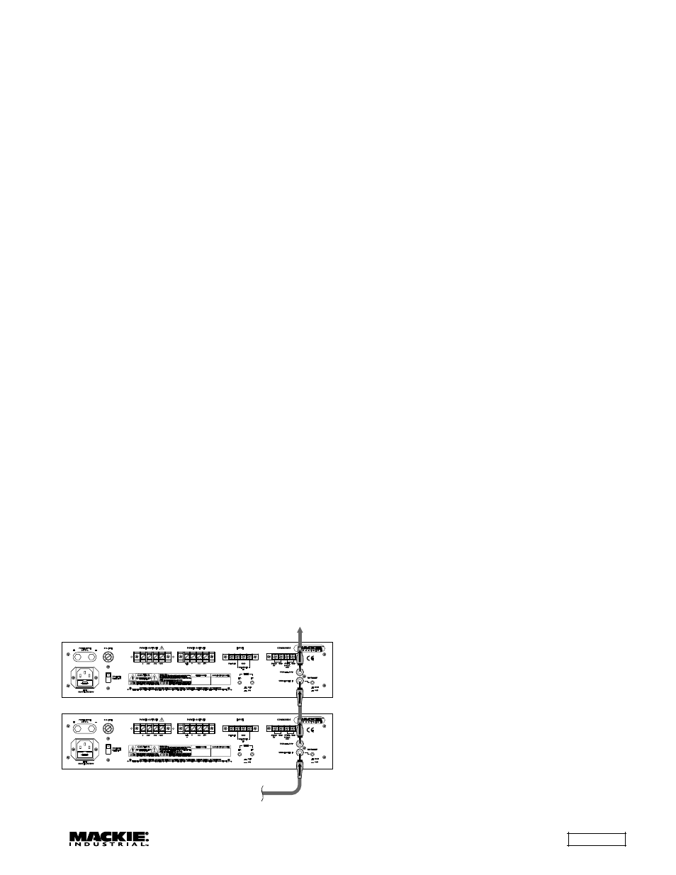
Using the PARALLEL OUT
The PARALLEL OUT connector is provided to
connect the UNBALANCED IN signal to multiple
amplifiers in a daisy-chain configuration.
COMMANDS STANDBY
An external normally-open switch can be
connected between the STANDBY terminal and the
GND terminal on the COMMANDS barrier strip on the
rear panel. Closing the switch enables the signal to
pass through the amplifier, and opening the switch puts
the amplifier in standby mode (power on, no signal).
Note: The UP4000 Series is shipped with the
Standby Mode disabled. Move jumper J1 on the
input board to enable the Standby Mode (see
instructions on page 8).
OVERL.
Connect an LED or relay between this terminal
and the GND terminal to provide an external
indication if the overload circuit has been activated.
It provides +18 VDC with a maximum output
capacity of 300mA when activated. See "Application
Diagram" on page 6.
POWER OUTPUTs
The amplifier outputs on the UP4000 Series can
be used with a 4-ohm impedance load, or to directly
drive a 25V, 50V, 70V, or 100V distributed system
(constant-voltage system).
Direct Speaker Connection
If the UP4000 Series is not being used in a
distributed speaker system, you can connect a
speaker with a 4-ohm load between the "4
Ω"
terminal and the "0" terminal.
Distributed Speaker System
When using the UP4000 Series in a distributed
system, connect the distributed system between
the appropriate POWER OUTPUT terminal (25V, 50V,
70V, or 100V) and the "0" terminal. Make sure the
speakers in the system are tapped appropriately so
they do not exceed the rated power of the amplifier.
(AM4060 = 60 watts, AM4120 = 120 watts,
AM4160 = 160 watts).
POWER INPUT 24V D.C.
The UP4000 Series can be powered using a 24
VDC power supply. This can serve as the primary
power supply for the UP4000 Series, or as a
backup supply in case of an AC power failure. The
UP4000 Series seamlessly switches to the backup
supply if there is a power loss. When both AC power
and 24 VDC power are connected, the AC power is
used and no current is drawn from the DC supply.
Note: The unit is not equipped with battery
charging capability.
From Signal
Source
To Next
Amplifier
UP4000 Series Daisy-Chaining Inputs