Connections, Connecting the input, Connecting the unbalanced in – MACKIE UP4161 User Manual
Page 7: Connecting the speakers, Connecting the power input 24v.d.c
UP4000 – 7
Connections
Connecting the INPUT
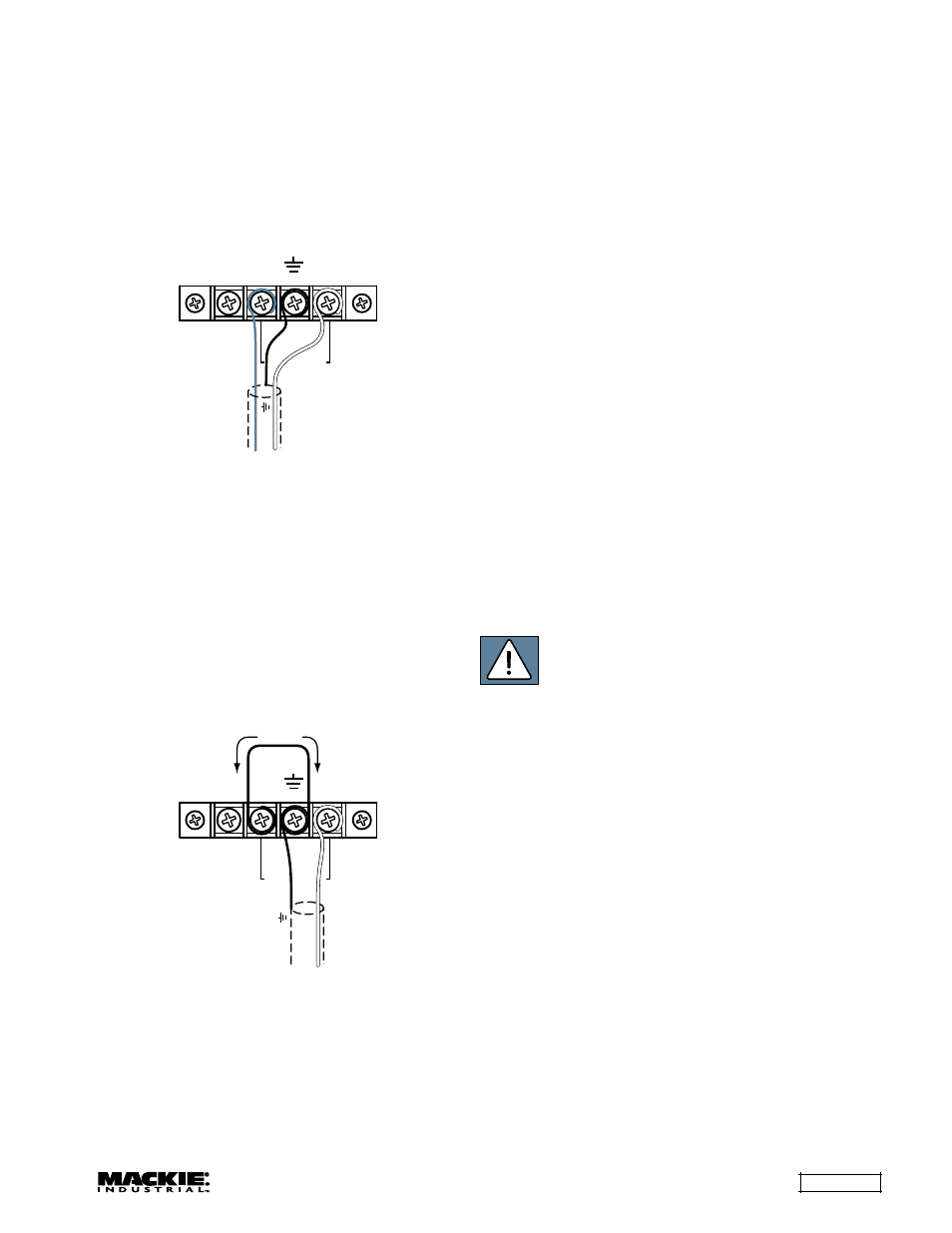
The Input has a balanced screw terminal
connector that accepts a line-level signal. The screw
terminals should be connected as shown in the
following figure:
+
–
PRIORITY
GND
BALANCED
IN
COLD (–)
HOT (+)
SHIELD
Strip the wire back about 1/2" inch, loosen the
screw enough to loop the wire around the shaft of
the screw (clockwise), and tighten down the screw
with either a slot-head or phillips-head screwdriver.
Use high-quality, three-conductor shielded cable
for balanced connections. The better the shield, the
better the audio signal is protected from induced
EMI and RFI.
If connecting an unbalanced line-level signal to
the Input, wire the connections as shown in the
following figure:
+
–
PRIORITY
GND
BALANCED
IN
JUMPER
SHIELD
HOT (+)
INPUT Terminal Strip: Balanced Connection
Connecting the UNBALANCED IN
The UNBALANCED IN uses an RCA-type
connector. It accepts a line-level signal (–10 dBV)
with the SENSITIVITY switch in the 0 dB position
(pushed IN). When connecting a low-level signal,
push the SENSITIVITY switch OUT (20 dB position).
Use high-quality, two-conductor shielded cable to
make these connections.
Connecting the Speakers
The speaker output connectors are screw
terminals. Use 16 or 18 gauge wire for connecting
the amplifier outputs to the speakers. Strip the wire
back about 1/2" inch, loosen the screw enough to
loop the wire around the shaft of the screw
(clockwise), and tighten down the screw with a slot-
head screwdriver.
If using a 4-ohm speaker, connect the 4
Ω output
terminal to the "+" terminal on the speaker, and
connect the "0" output terminal to the "–" terminal
on the speaker.
If using a constant-voltage distributed speaker
system, connect either the 25V, 50V, 70V, or 100V
output terminal to the "+" side of the speaker system,
and connect the "0" output terminal to the "–" side of
the speaker system. Make sure that the taps on the
speakers add up to no more than the rated power
for the UP4000 Series Amplifier being used.
CAUTION: To prevent the risk of electric
shock, never touch the bare wires coming
from the OUTPUT TERMINALS of the
amplifier when it is switched on.
When the connections have been made, insulate
the 50V, 70V, and 100V terminals of the amplifier
using the protective cover supplied.
Connecting the POWER INPUT 24V.D.C.
Connect a 24 VDC power supply to these spring
terminals as an alternate method to power the
UP4000 Series. To minimize the voltage drop across
the wire and prevent overheating, use at least 16
AWG wire for the UP4061, and 14 AWG wire for
the UP4121 and UP4161.
INPUT Terminal Strip: Unbalanced Connection