Attaching chute assembly, Attaching chute directional control – MTD 615 User Manual
Page 8
8
IMPORTANT:
If the right hand lock-out cable is not
adjusted correctly, the wheels will tend to turn. If the left
hand lock-out cable is not adjusted correctly, the
augers will keep on rotating.
NOTE: Please note that the drive clutch cable on units
with 16” wheels is routed under the axle. In other units,
the cable is routed over the axle.
WARNING:
Do not over-tighten the clutch
cables. Tension on either cable in the
disengaged (up) position may override the
safety features of the machine.
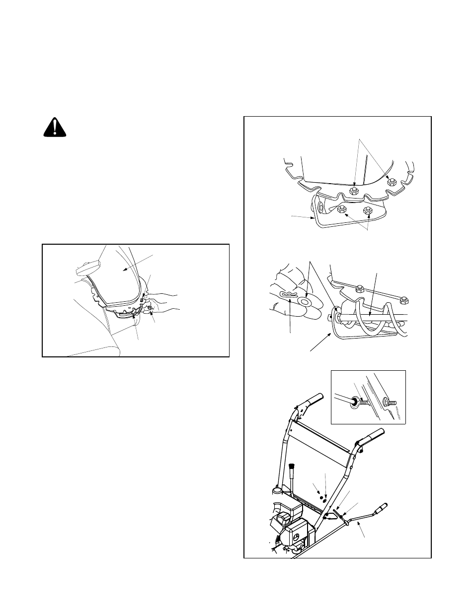
Attaching Chute Assembly
(Hardware Group E)
•
Place chute assembly over chute opening, with the
opening in the chute assembly facing the front of
the unit.
•
Place chute flange keepers beneath lip of chute
assembly, with the flat side of chute flange keeper
facing downward. See Figure 8.
Figure 8
•
Insert two hex bolts up through each chute flange
keeper and chute assembly. Secure with hex lock
nuts.
•
After assembling all three chute flange keepers,
tighten all nuts and bolts securely. Do not over-
tighten.
NOTE: Lock nuts cannot be threaded onto a bolt by
hand. Tighten with two 7/16” or adjustable wrenches.
Attaching Chute Directional Control
(Hardware Group F)
•
Loosen the two hex nuts which secure the lower
chute directional control support bracket to the
snow thrower housing. See Figure 9.
•
Place one flat washer over the end of the chute
directional control, then insert the end of the chute
directional control into the hole in the plastic
bushing on the chute bracket. Place the second flat
washer on chute directional control and secure with
hairpin clip. See Figure 9.
•
Thread one hex nut onto the eyebolt on the chute
directional control assembly until there is at least
two inches of threads showing between the nut and
the eyebolt head.
•
Place the eyebolt into the hole located half way up
the left handle. Secure with cupped washer and
hex nut making sure that the cupped side of the
washer is against the handle.
Figure 9
Chute Assembly
Hex Bolt
Hex Lock Nut
Chute Flange
Keeper
Hex Bolts &
Hex Lock Nuts
Lower
Chute
Directional
Control
Bracket
Hex Nuts
Hairpin Clip
Flat
Washers
Chute Directional
Control
Chute Directional
Control Bracket
Eye Bolt
Cupped
Washer
Hex Nut
2” of thread
Hex Nut
Chute Directional
Control