Shave plate and skid shoes, Belt removal and replacement – MTD 615 User Manual
Page 16
16
IMPORTANT:
NEVER replace the auger shear bolts with
standard hex bolts. Any damage to the auger gearbox
or other components as a result of doing so will NOT be
covered by your snow thrower’s warranty.
Shave Plate and Skid Shoes
The shave plate and skid shoes on the bottom of the
snow thrower are subject to wear. They should be
checked periodically and replaced when necessary.
•
To remove skid shoes, remove the four carriage
bolts, cupped washers and hex nuts which attach
them to the snow thrower. Reassemble new skid
shoes with the four carriage bolts, cupped washers
(cupped side goes against skid shoes) and hex
nuts. Refer to Figure 16.
•
To remove shave plate, remove the carriage bolts,
cupped washers and hex nuts which attach it to the
snow thrower housing. Reassemble new shave
plate, making sure heads of carriage bolts are to
the inside of housing. Tighten securely.
Belt Removal and Replacement
WARNING:
Disconnect the spark plug wire
from the spark plug and ground.
Auger Belts
•
Remove plastic belt cover from front of the engine
by removing the two self-tapping screws.
See Figure 20.
•
Drain gasoline from the snow thrower or place a
piece of plastic under the gas cap.
•
Tip the unit up and forward so that it rests on auger
housing.
Figure 20
•
Remove six self-tapping screws from the frame
cover underneath the snow thrower.
•
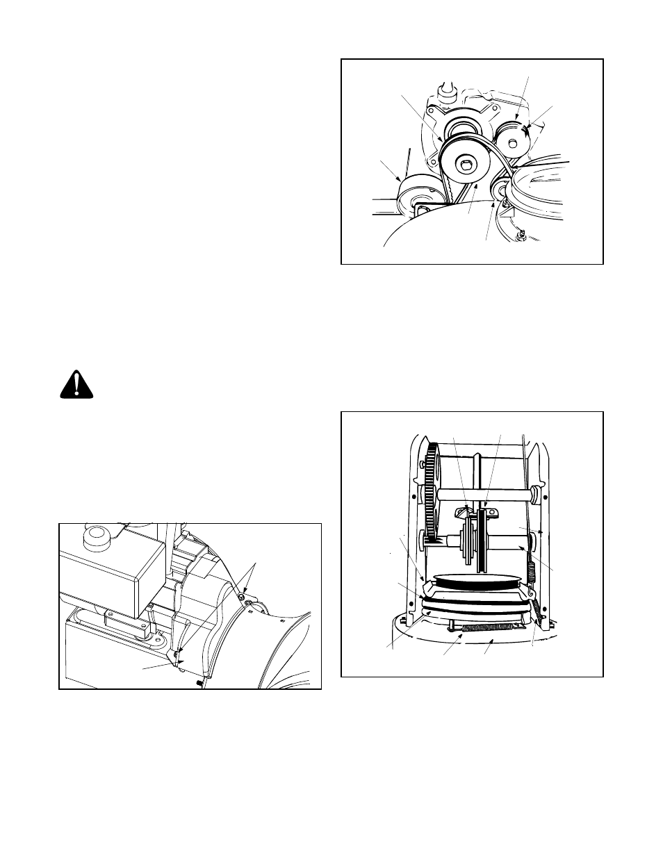
Roll auger belt(s) off engine pulley. See Figure 21.
•
Unhook the idler spring from the hex bolt on the
auger housing. See Figure 22.
•
Unhook the support bracket spring from the frame.
Figure 21
NOTE: It may be necessary to loosen the six nuts that
connect the frame to the auger housing to aid in belt
removal. 5.0 HP models has only one auger belt.
•
Lift the rear auger belt from the auger pulley, and
slip belt between the support bracket and the auger
pulley. Repeat this step to remove the front auger
belt. See Figure 22.
•
Reassemble auger drive belt(s) by following
instructions in reverse order.
Figure 22
Self-Tapping
Screw
Belt Cover
Drive Belt
Drive
Idler
Engine
Pulley
Idler
Auger
Belt
Pulley
Pulley
Pulley
Pin
Friction Wheel
Frame
Auger Belt
Auger
Pulley
Support
Bracket
Gear
Shaft
Assembly
Support Bracket
Spring
Idler
Spring
Auger
Housing