Warning, General installation (options), Fig. 11 fig. 12 – Marley Engineered Products 994 User Manual
Page 7: Fig. 13 fig. 14
— 7 —
120 V. A.C.
SUPPLY
CEILING BOX
CEILING BOX
GROUND
BLACK
GROUND
BLACK
WHITE
BLUE
WHITE
WHITE
BLACK
BLUE
GREEN
GREEN
CEILING
CEILING
BALL HANGER GROUND
WIRE SET SCREW
BALL HANGER GROUND
WIRE SET SCREW
BALL HANGER
SET SCREW
BALL HANGER
SET SCREW
BALL HANGER
BALL HANGER
CANOPY
CANOPY
MOTOR
SET SCREW
MOTOR
SET SCREW
MOTOR
HOUSING
TOP
MOTOR
HOUSING
TOP
WALL MOUNTED
LIGHT SWITCH
OR DIMMER
(USE ONLY LISTED
GENERAL USE
SWITCHES)
WALL CONTROL
CIRCUIT
GROUND
WHITE
GND.
BLACK
BLACK
BLACK
WHITE
WHITE
120 V. A.C.
SUPPLY
FIG. 11
FIG. 12
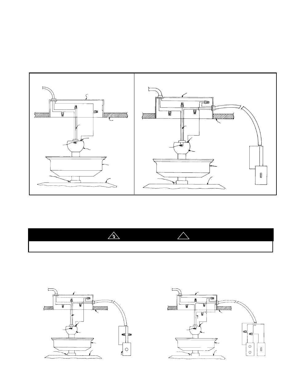
GENERAL INSTALLATION (OPTIONS)
Various options for installing and operating these ceiling fans and accessories are available. Wiring diagrams are shown
on the following pages. Refer to the instructions included with the light kit and/or speed control where applicable.
OPTION #1 (Fig. 11) Fan and light controlled at unit.
This installation is the simplest with all controls mounted on the fan as shipped. The light kit, if used, is controlled with the
pull-chain switch on the light kit.
OPTION #2 (Fig. 12) Fan controlled at unit. Light controlled at wall with switch or dimmer.
This option is the same as Option #1, except the light is controlled from an existing wall-mounted switch or light dimmer.
This option is designed for installations in which the fan is installed in place of a ceiling light or chandelier which was
controlled by a wall switch. No additional wiring is necessary.
OPTION #3 (Fig. 13) Light controlled at unit. Fan controlled at wall by a Speed Control.
This option utilizes a speed control (See Chart 1) to operate the fan from a remote wall location. The light is controlled at
the fan. The wall control replaces the existing wall switch. No additional wiring is necessary for this installation. The Fan
switch on the unit must be left in the high speed position for the control to function properly. We suggest you cut off the
chain of the pull-chain switch after the high speed position is established on the fan.
OPTION #4 (Fig. 14) Light controlled at wall. Fan controlled at wall by a Speed Control.
This option can be used when the fan is installed in place of an existing ceiling light kit. A speed control (See Chart 1) will
replace the light switch (or dimmer) in the wall that controlled the ceiling light. An additional box and switch must be
installed for this option. Follow all state and/or local building and electrical codes for this installation.
120 V. A.C.
SUPPLY
CEILING BOX
CEILING BOX
GROUND
BLACK
GROUND
BLACK
WHITE
BLACK
WHITE
BLACK
WHITE
WHITE
BLACK
GND.
BLUE
BLUE
GREEN
GREEN
CEILING
CEILING
BALL HANGER GROUND
WIRE SET SCREW
BALL HANGER GROUND
WIRE SET SCREW
BALL HANGER
SET SCREW
BALL HANGER
SET SCREW
BALL HANGER
BALL HANGER
CANOPY
CANOPY
MOTOR
SET SCREW
MOTOR
SET SCREW
MOTOR
HOUSING
TOP
MOTOR
HOUSING
TOP
SPEED CONTROL
(USE ONLY LISTED
CONTROLS)
SPEED CONTROL
(USE ONLY LISTED
CONTROLS)
WALL MOUNTED
LIGHT SWITCH
OR DIMMER
(USE ONLY LISTED
GENERAL USE
SWITCHES)
WALL CONTROL
CIRCUIT
WALL CONTROL
CIRCUIT
GROUND
GROUND
WHITE
BLACK
BLACK
WHITE
WHITE
RED
WHITE
GND.
RED
BLACK
BLACK
BLACK
BLACK
WHITE
WHITE
120 V. A.C.
SUPPLY
FIG. 13
FIG. 14
RISK OF FIRE - Fan speed switch must be set to high when wall speed control is used.
WARNING
!