Section 3 − installation, 1. specifications, 2. site selection – Miller Electric 22A User Manual
Page 13
OM-193 472 Page 9
SECTION 3 − INSTALLATION
3-1. Specifications
Type of Input
Power
Welding Power
Source Type
Wire Feed
Speed Range
Wire
Diameter
Range
Welding
Circuit Rating
Overall
Dimensions
Weight
24 Volts AC Single
Phase
7 Amperes 50/60
Hz
Constant Voltage
(CV) DC With
14-Pin And
Contactor Control
75 to 750 ipm
(1.9 To 19 mpm)
.023 To 5/64 in
(0.6 To 2 mm)
Max Spool Weight:
60 lb (27 kg)
100 Volts,
500 Amperes,
100%
Duty Cycle
Length: 23-1/2 in
(597 mm)
Width: 10-3/4 in
(273 mm)
Height: 11 in
(279 mm)
35 lb (15.9 kg)
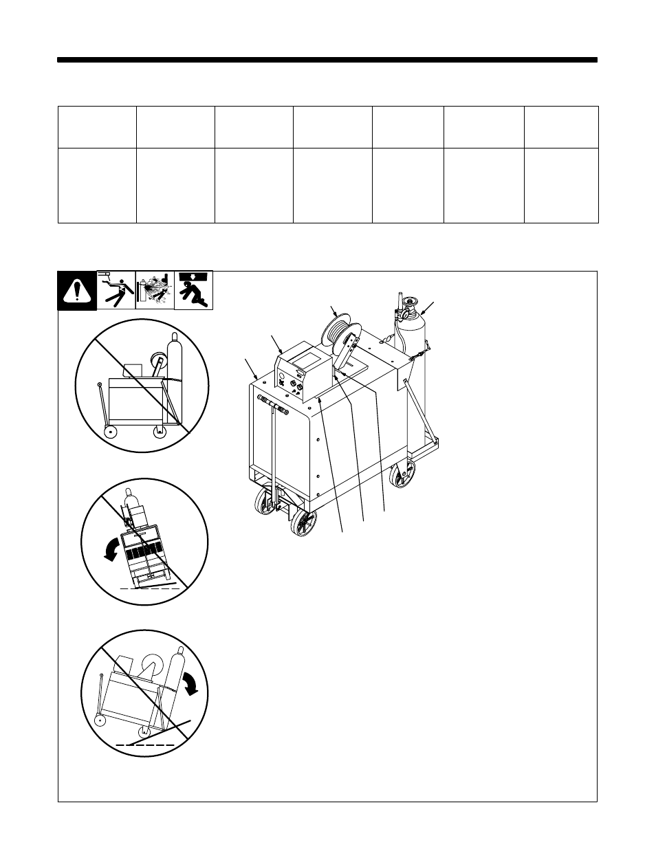
3-2. Site Selection
802 348-A / Ref. 152 468-A / 155 242 / 801 919-B
1
Wire Feeder
2
Lifting Eye
3
Rubber Feet
4
Slot
Choose slot that allows all rubber
feet to sit securely on top of welding
power source.
5
Wire Spool/Reel
6
Gas Cylinder (Customer
Supplied)
.
Shielding gas pressure not to
exceed 100 PSI (689 kPa).
7
Welding Power Source
Y Do not put feeder where
welding wire hits cylinder.
Y Do not move or operate
equipment when it could tip.
2
4
3
1
5
6
7