Scanner and cable terminations, Scanner pinout connections – Metrologic Instruments VOYAGERGS MS9590 User Manual
Page 36
32
S
CANNER AND
C
ABLE
T
ERMINATIONS
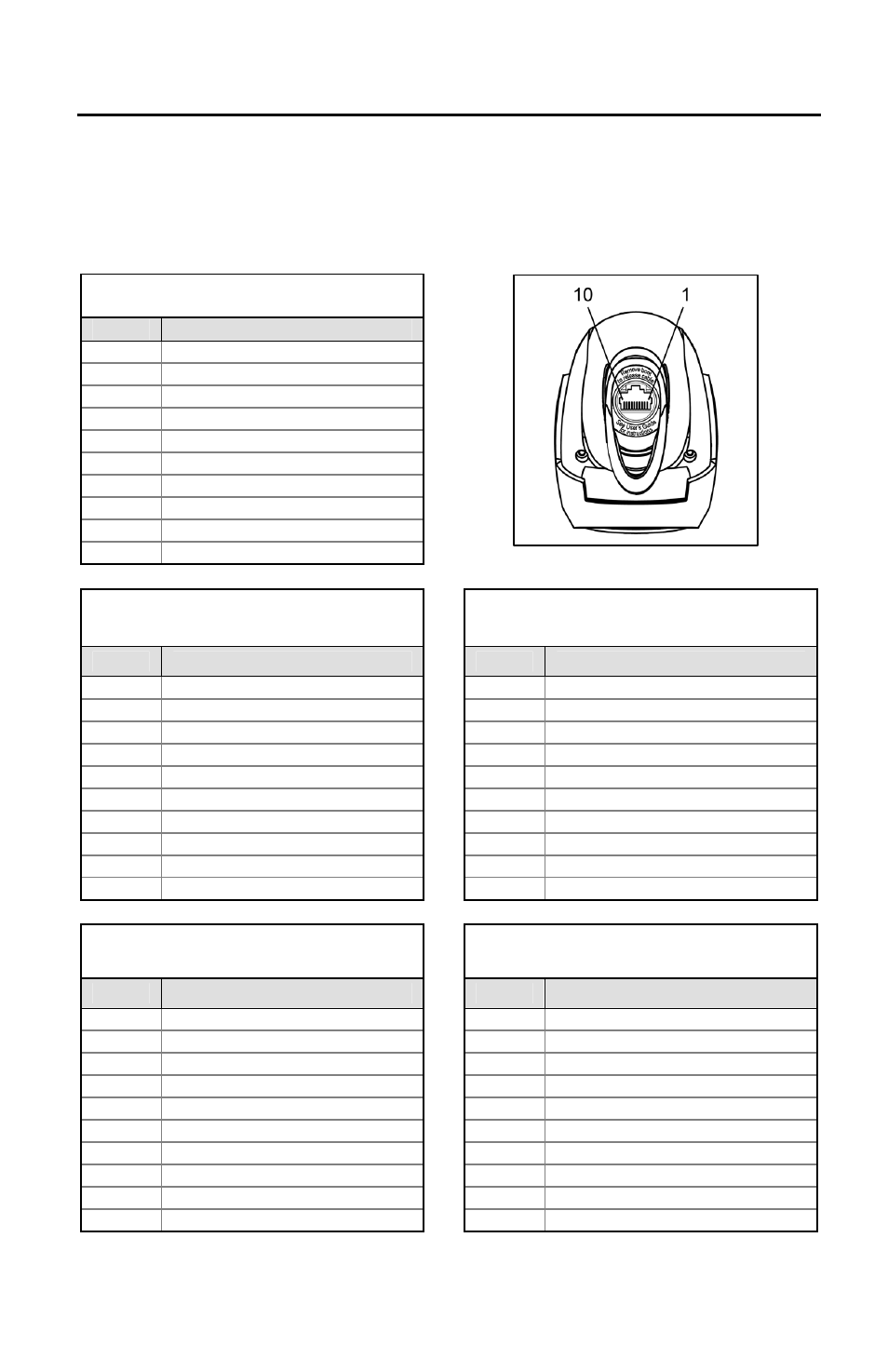
Scanner Pinout Connections
The MS9590 and MS9591 scanner interfaces terminate to a 10-pin modular jack.
The serial number label indicates the interface enabled when the scanner is
shipped from the factory.
MS9590-14 or MS9591-14
RS232
Pin
Function
1 Ground
2 Transmit
RS232
Output
3
Receive RS232 Input
4 RTS
RS232
Output
5
CTS RS232 Input
6
DTR RS232 Input
7 Reserved
8
DSR TTL Output
9 +5VDC
10 Shield
Ground
MS9590-47 or MS9591-47
Keyboard Wedge and Stand-Alone Keyboard
MS9590-38-EAS
USB and RS232 Transmit/Receive with EAS
Pin
Function
Pin
Function
1 Ground
1 Ground
2
Transmit RS232 TTL Output
2
Transmit RS232 Output
3
Receive RS232 TTL Input
3
Receive RS232 Input
4
PC Data TTL
4
EAS -
5
PC Clock TTL
5
EAS+
6
KB Clock TTL
6
D+
7
Reserved
7
PC +5V Detect Input
8
KB Data TTL
8
D-
9
PC +5VDC
9
PC +5V Power
10 Shield
Ground
10 Shield
Ground
MS9590-106 or MS9591-106
RS485
, USB
MS9590-40-EAS
USB RS485
OEM with EAS
Pin
Function
Pin
Function
1 Ground
1 Ground
2
Transmit RS232 TTL Output
2
Transmit RS232 Output
3
Receive RS232 TTL Input
3
Receive RS232 Input
4 IBM
+
4 EAS
-
5 IBM
-
5 EAS+
6 D+
6 D+
7
PC +5V Detect Input
7
PC +5V Detect Input
8 D-
8 D-
9
PC +5V Power
9
PC +5V Power
10 Shield
Ground
10 Shield
Ground
Applicable for IBM
®
host applications
Figure 25.