Op erat ing th e kvm extend er usb system, Saf ety, Technical sp ecif icatio ns – Minicom Advanced Systems KVM EXTENDER USB 5UM30167 User Manual
Page 2
QUICK START GUIDE
4
5.3 Connecting the System cable
Connect the System cable CAT5/6/7 FTP cable to the System ports of the Transmitter
and Receiver.
5.4 Connecting to the power supply
The Transmitter receives its power from the connected computer and does not
generally need an external power supply. However, when the Transmitter is connected
to a KVM switch it may need an external power supply. Use a Minicom Power
adapter 12VDC 1A, ordered separately p/n
5
PSA70020.
Connect the Receiver to the power supply with the Power adapter and cord provided.
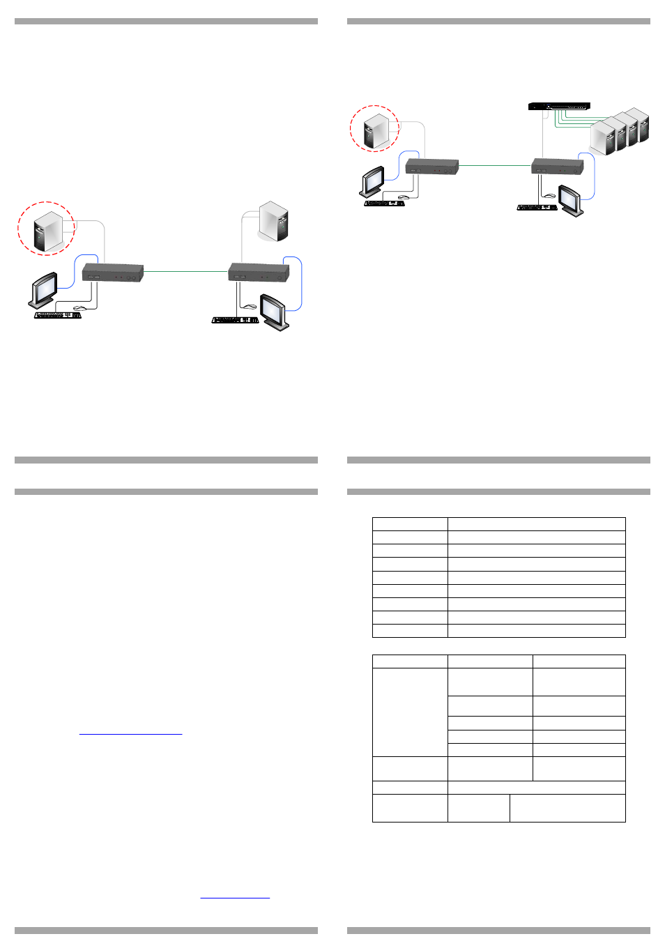
6. Ext ender s ystem with opt ional comput er at
Receiv er p osit ion
You can connect a computer to the Receiver position. The Receiver position can then
either control the local computer or the Transmitter position computer.
Receiver
Transmitter
Local User
position
Extended User
position
CAT5 cable - 150m/500ft
Optional PC
Figure 7 Extender system with optional computer at Receiver position
The connections are the same as outlined above, with the addition of a
computer connected to the Receiver as follows:
6.1 Connecting a computer to the Receiver
Connect a VGA + USB cable to the Receiver and a computer. Connect the HD15
connector to the Receiver Computer port and connect the VGA and USB connectors
to the computer Monitor and USB ports.
KVM EXTENDER USB
5
7. Ext ender + KVM swit ch system with o pt ional
comput er at Receiv er po sit ion
You can connect a KVM switch to the Receiver position. The Receiver position can
then either control the local computer or any computer connected to the KVM switch
at the Transmitter position computer.
I0
1
2 3
4 5
6
7 8
1
0
1
1
1
2
1
3
1
4
1
5
1
6
9
Receiver
Transmitter
Local User
position
KVM Switch
Extended User
position
CAT5 cable - 150m/500ft
Optional PC
Figure 8 Extender + KVM switch with optional computer at Receiver position
The connections are the same as outlined above, with the addition of a KVM
switch connected to the Transmitter as follows:
Connect a VGA + USB cable to the Transmitter and the KVM switch. Connect
the HD15 connector to the Transmitter Computer port and connect the VGA
and USB connectors to the KVM switch Monitor and USB ports.
8. Op erat ing th e KVM Extend er USB system
The system works on a first come first served basis – press the keyboard or move the
mouse at either the Transmitter (where relevant) or Receiver position to take control
of the Transmitter position computer.
Transmitter position: Press the Lock button to keep/gain control of the computer at
the Transmitter position. The Lock LED at the Transmitter position illuminates and
blinks at the Receiver position. The Control LED at the Transmitter position
illuminates.
Receiver position: Press the Lock button to keep control of the Transmitter computer
at the Receiver position. The Lock LED at the Receiver position illuminates and
blinks at the Transmitter position.
Press the Local button to gain control of the Receiver computer position. The Local
LED blinks.
QUICK START GUIDE
6
Note! You can only gain control by pressing the Lock button if the Lock LED is
currently not blinking.
Re-pressing the Lock button at either position releases control and the Lock LEDs
turn off.
8.1 Keyboard hotkeys
To toggle between the Transmitter and the Receiver position, press: Caps Lock twice,
release, then press C.
To turn the beeper sound on/off, press: Caps Lock twice, release, then press B.
8.2 Adjusting the picture
At the Receiver, you can adjust the picture quality using a small screwdriver to turn
the Luminance and Equalization Picture adjusters located on the Receiver’s rear
panel.
9. Saf ety
The device must only be opened by an authorized Minicom technician. Disconnect
device from AC mains before service operation!
9.1 User guide feedback
Your feedback is very important to help us improve our documentation. Please email
any comments to:
Please include the following information: Guide name, part number and version
number (as appears on the front cover).
9.2 WEEE compliance
WEEE Information for Minicom Customers and Recyclers
Under the Waste Electrical and Electronic Equipment (WEEE) Directive and
implementing regulations, when customers buy new electrical and electronic
equipment from Minicom they are entitled to:
· Send old equipment for recycling on a one-for-one, like-for-like basis (this
varies depending on the country)
· Send the new equipment back for recycling when this ultimately becomes
waste
Instructions to both customers and recyclers/treatment facilities wishing to obtain
disassembly information are provided in our website
KVM EXTENDER USB
7
10. Technical sp ecif icatio ns
System cable
CAT5/6/7 FTP 2x4x24 AWG Solid Wire cable
Maximum distance
150m/500ft
Mouse support
USB mouse
Operating systems
All major operating systems
Management
Push button or external control unit
Screen resolution
Up to 1600X1200 @ 75Hz
Operating temperature
0°C to 40°C/32°F to 104°F
Storage temperature
-40°C to 40°C/-40°F to 104°F
Warranty
3 Years limited
Transmitter
Receiver
HDD15F (VGA + USB
cable) – for computer or
KVM switch
HDD15F (VGA + USB cable)
- for optional local computer
USB X 2: for Keyboard +
Mouse
USB X 2: for Keyboard +
Mouse
HDD15 : for monitor
HDD15 : for monitor
RJ45 - System
RJ45 - System
Cables & connectors
RJ11 - External control unit RJ11 - External control unit
Dimensions
85 x 113 x 25mm/
3.3 x 4.4 x 0.98 inches
85 x 49 x 25mm/
3.3 x 4.4 x 0.98 inches
Shipping weight
1,750g/3.9lb
Power supply
From computer or
external power
adapter 12VDC 1A
External power adapter 12VDC 1A
© 2010 Minicom Advanced Systems Limited. All rights reserved.